Self-locking osteosynthesis device

a self-locking, osteotomy technology, applied in the field of self-locking osteosynthesis or osteotomy devices, can solve the problems of difficult practical creation of a device of this type, no possibility to choose the orientation of the screws, and the thickness of the plates, so as to achieve the effect of significantly reducing the dimension of the plates that can be used

Inactive Publication Date: 2006-06-01
BIOTECH INT
View PDF22 Cites 111 Cited by
  • Summary
  • Abstract
  • Description
  • Claims
  • Application Information

AI Technical Summary

Benefits of technology

[0013] The invention has the purpose of correcting the shortcomings mentioned above for osteosynthetic systems using plates and screws, notably because of the fact that the existing devices for serious orthopedics (treatment of serious traumatisms) can not be transposed to hand and foot surgery in which the dimension of the plates that can be used becomes considerably reduced.
[0020] In addition to obtaining the results mentioned above that are very much of interest, the osteosynthesis device according to the invention provides several advantages:
[0021] it has a simple design so that it can be made in an economical manner;
[0025] This osteosynthesis device thus meets perfectly the expectations of surgeons in terms of ease of implementation and reliability of usage.

Problems solved by technology

However, these relatively complex devices require the use of plates having a relatively sizeable thickness that is totally incompatible with a usage for operations on the bones of the hand or foot, for which the thickness of the plates must be as reduced as possible, taking into account the small size of the bones involved.
A device of this type can only be planned for the reduction of identical fractures, because otherwise it would be necessary to provide as many plate models as possible cases of fractures, which is practically impossible; in fact, it does not offer any possibility to choose the orientation of the screws as a function of the problems encountered in orthopedic surgery.
The practical creation of a device of this type would be difficult and it seems its effectiveness has not been established.
In a general manner, in the field of osteosynthesis of small bones requiring the use of plates having small dimensions, the devices that are currently available on the market do not make possible an angular clearance between the screws and the plate, so that the screws thus have to be positioned perpendicularly to the plate.

Method used


Image

  • Self-locking osteosynthesis device
  • Self-locking osteosynthesis device
  • Self-locking osteosynthesis device

Examples


Embodiment Construction

[0034] Reference is made to the drawings in order to describe an embodiment example that is of interest, though in no way restrictive, of the self-locking osteosynthesis device according to the invention.

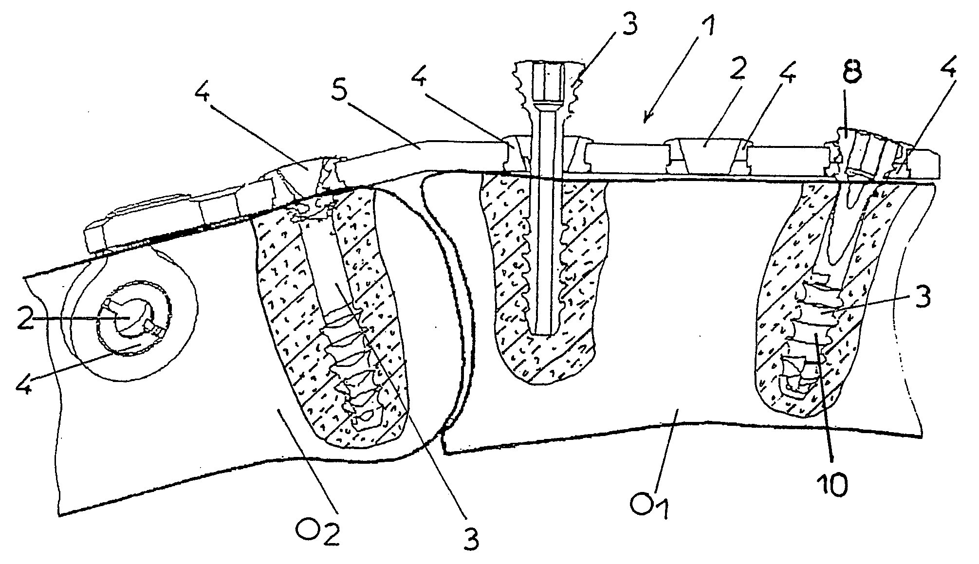
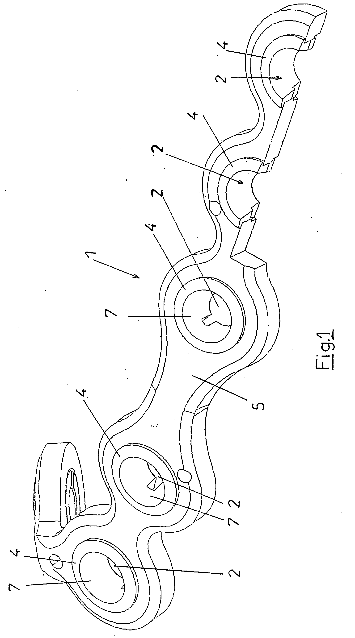
[0035] This device comprises a plate 1 equipped with passage holes 2 and fixation screws 3.

[0036] According to the invention, the plate 1 is made, at least in the defining zones of the passage holes 2 of the screws 3, of a material 4 that has the mechanical properties that allow a self-locking of the periphery of these holes using tapping screws for the fixation of the plate on the bone material.

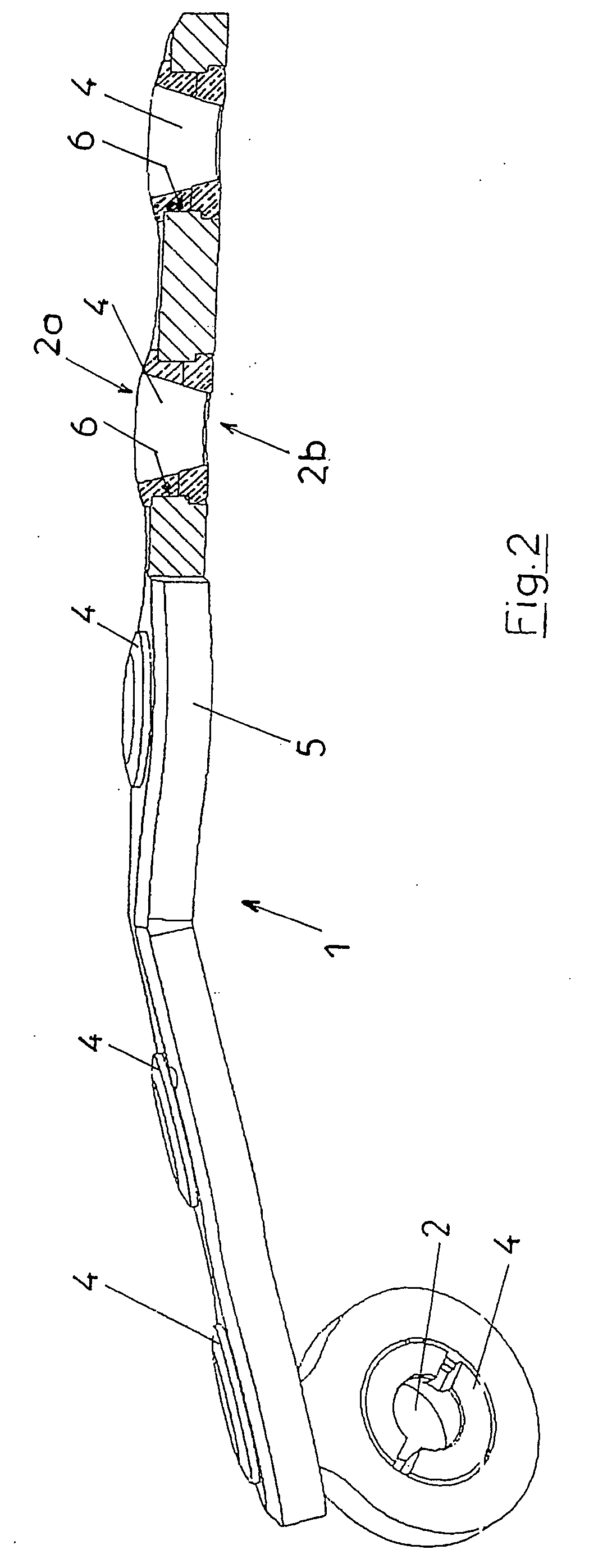
[0037] The plate 1 can have any shape designed for the cases to be treated with reduction of fractures or restorative surgery; the shape shown in FIG. 1 is thus only a possible example of the shape, and the same applies for the placement of the holes 2 in the plate.

[0038] In a preferred manner, the plate 1 is made up of a composite plate whose peripheries 4 of the holes 2 are made of a p...


PUM


Abstract

The self-locking osteosynthesis device includes a plate equipped with holes for the passage of fixation screws. The invention is characterised in that, at least in the areas defining the screw holes, the aforementioned plate is made from a material having mechanical properties such that the periphery of the holes can be self-tapped by means of tapping screws which can be used to fix the plate.

Description

RELATED U.S. APPLICATIONS [0001] Not applicable. STATEMENT REGARDING FEDERALLY SPONSORED RESEARCH OR DEVELOPMENT [0002] Not applicable. REFERENCE TO MICROFICHE APPENDIX [0003] Not applicable. FIELD OF THE INVENTION [0004] The invention relates to a self-locking osteosynthesis or osteotomy device of the type comprising a plate having an appropriate shape designed to be affixed on bone fragments using a screw to ensure their coaptation. BACKGROUND OF THE INVENTION [0005] The coaptation of the bone fragments using plates of titanium or another material and screws in order to create an osteosynthesis is a common operation in bone surgery, for example, orthopedic surgery. [0006] In order to obtain a good result, it is necessary that the plates or implants are screwed together permanently to the bone fragments assembled from the implants. It is thus a requirement that the screws can not unscrew and move back, to prevent any displacement of the implants relative to the bone fragments. [000...

Claims


Application Information

Patent Timeline
Patent Type & Authority Applications(United States)
IPC IPC(8): A61F2/30A61B17/80A61B17/86
CPCA61B17/8057A61B17/864A61B17/8605A61B17/8085
Inventor IMPELLIZZERI, FREDERIC
Owner BIOTECH INT
Why Eureka
Try Eureka