Heat exchanger tubing by continuous extrusion

a technology of heat exchanger tubing and extrusion pressure, which is applied in the direction of lighting and heating apparatus, transportation and packaging, coatings, etc., can solve the problems of increasing the extrusion pressure needed to extrude the heat exchanger tube, increasing the cost of heat exchanger tube production, and at the least, difficult (or sometimes impossible) to produce fine dimensioned tubing from high strength materials using traditional extrusion methods. , to achieve the effect of reducing manufacturing times, reducing

Inactive Publication Date: 2006-06-08
ARCONIC INC
View PDF22 Cites 43 Cited by
  • Summary
  • Abstract
  • Description
  • Claims
  • Application Information

AI Technical Summary

Benefits of technology

This patent describes how to make better quality heat exchanger tubes made from stronger materials like aluminum that are cheaper and can be produced faster. These new tubes also have increased resistance to high pressure levels which makes them more durable than previous versions.

Problems solved by technology

The technical problem addressed in this patent is the challenge of producing small, highly detailed parts called heat exchanger tubes from strong aluminum alloys without introducing excessively high levels of strain during the extrusion process. Billet-based extrusion methods offer limited options when trying to achieve both high strength and small sizes simultaneously, leading to increased expense and limitations in alloy selection and processing techniques. The solution presented involves a new method called conformational rotation extrusion (Conform™ Process), but its effectiveness depends upon the complexity of the final design and requires careful consideration of various factors including material properties, machine tool availability, etc.

Method used


Image

  • Heat exchanger tubing by continuous extrusion
  • Heat exchanger tubing by continuous extrusion
  • Heat exchanger tubing by continuous extrusion

Examples


Embodiment Construction

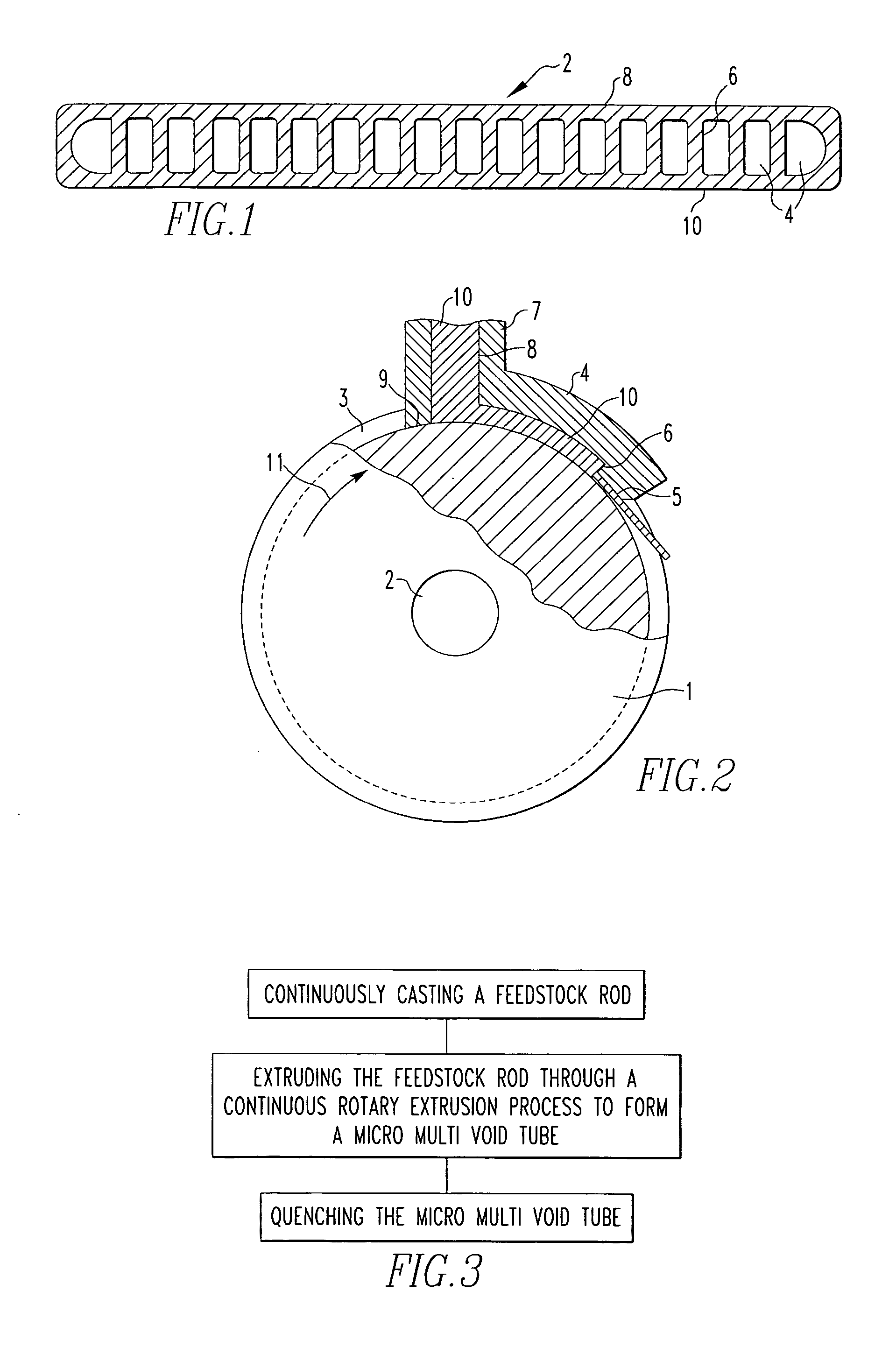
[0052] The accompanying drawings and the description which follows set forth this invention in its preferred embodiments. However, it is contemplated that persons generally familiar with extrusion processes will be able to apply the novel characteristics of the structures and methods illustrated and described herein in other contexts by modification of certain details. Accordingly, the drawings and description are not to be taken as restrictive on the scope of this invention, but are to be understood as broad and general teachings. When referring to any numerical range of values, such ranges are understood to include each and every number and / or fraction between the stated range minimum and maximum. For purposes of the description hereinafter, the terms “upper”, “lower”, “right”, “left”, “vertical”, “horizontal”, “top”, “bottom”, and derivatives thereof shall relate to the invention as it is oriented in the drawing figures.

[0053] This invention solves the difficulty of extruding a ...


PUM

PropertyMeasurementUnit
Temperatureaaaaaaaaaa
Lengthaaaaaaaaaa
Fractionaaaaaaaaaa

Abstract

A heat exchanger tube having enhanced corrosion resistance and improved resistance to high burst pressures. The heat exchanger tube comprises an aluminum alloy that consists essentially of about 0.01-1.5% silicon, up to about 1.2% copper, up to about 2.0% manganese, about 0.01-1.0% iron, about 0.01-5.0% zinc, up to about 0.02% titanium and the balance substantially aluminum and incidental elements and impurities.

Description


Claims


Application Information

Patent Timeline
Owner ARCONIC INC
Why Eureka
Try Eureka