Terminal computer display assembly

a technology of computer display and assembly, which is applied in the direction of machine supports, electrical apparatus casings/cabinets/drawers, instruments, etc., can solve the problems that no one can seem to prevent the monitor from falling instantaneously, and achieve the effect of saving space, preventing the monitor from falling suddenly or accidentally, and reducing the cost of operation

Inactive Publication Date: 2006-06-08
TUL CORP
View PDF7 Cites 25 Cited by
  • Summary
  • Abstract
  • Description
  • Claims
  • Application Information

AI Technical Summary

Benefits of technology

[0017] This invention neglects the need of using both hands when operating the monitor to move up or down, and has also no need to use the other hand to hold or support the monitor while moving it. The support of this invention is a combination of three major capabilities, namely adjustable height, able to be turned, and able to be inclined backwards. Furthermore, it also includes other useful functions such as the installation of the interface circuitry board into the base allowing other accessories to be plugged into thus achieving greater efficiency. In other words, this is a new invention for a LCD monitor-supporting device with base that has an interface for plugging other input / output devices into.
[0018] The support of this invention will also save space, unlike other previous cases where a large rotational space is required. Another characteristic of this invention is that a pressurized cylinder aids the height adjustment, and can effectively prevent the monitor from falling down suddenly or accidentally.

Problems solved by technology

The pin has to be pulled out and re-inserted every time when adjusting the height of the monitor, which can cause inconvenience when operating.
However, until now, due to certain mechanical structures of all of the relevant designs of height adjustment of monitors, none can seem to prevent the monitor from falling instantaneously.

Method used


Image

  • Terminal computer display assembly
  • Terminal computer display assembly
  • Terminal computer display assembly

Examples


Embodiment Construction

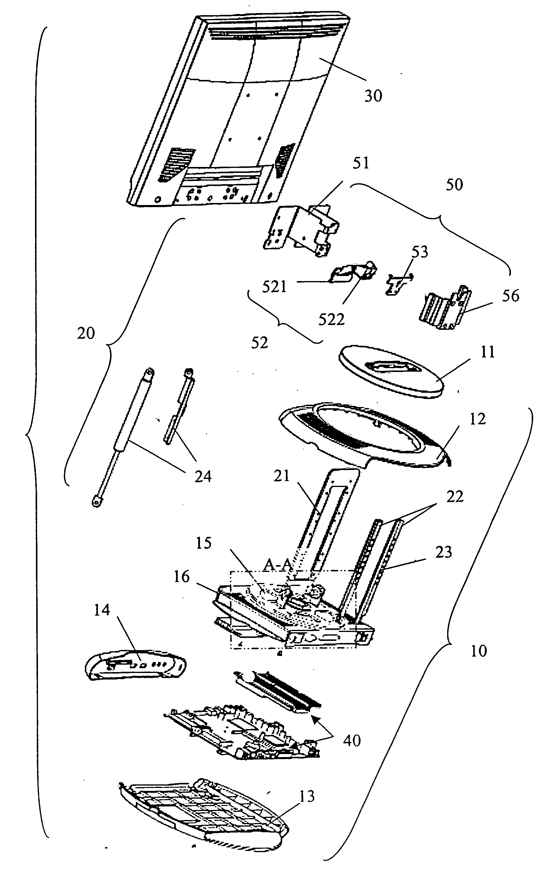
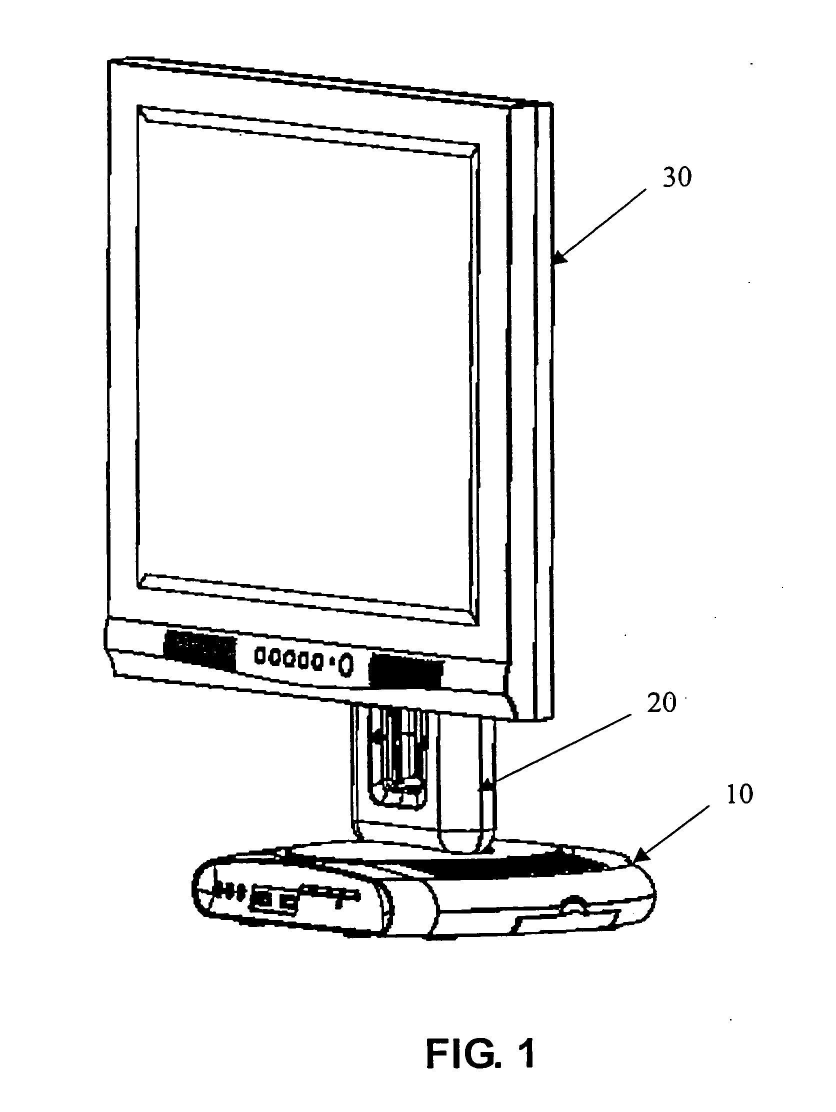
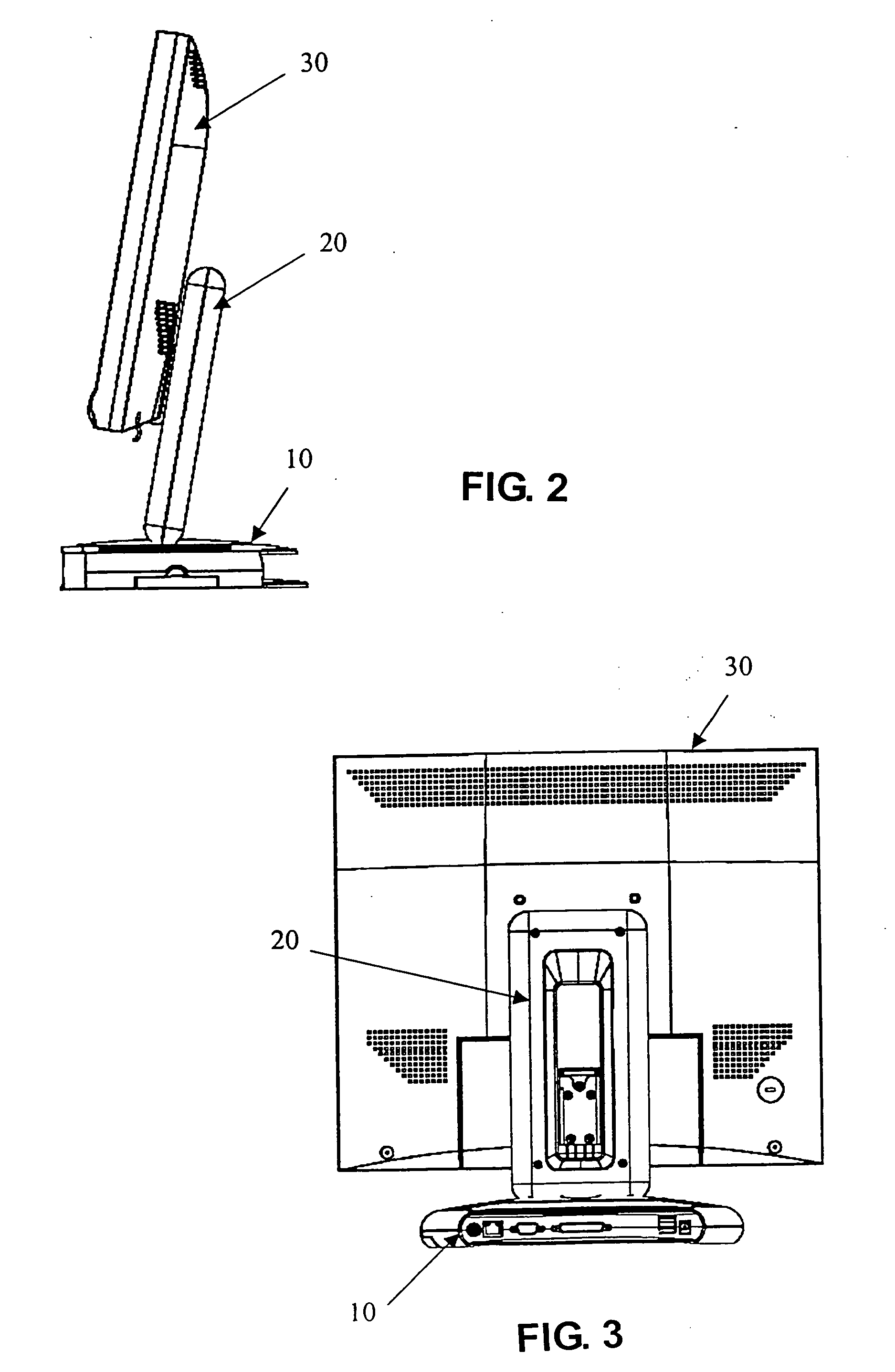
[0028] As FIG. 1 to FIG. 5 shows, specifically as shown in FIG. 2, the assembly of this invention consists of a base (10) and a support (20). The support (20) is used for securing a weight unit, in this embodiment, a monitor (30), and the monitor (30) will be able to rotate, incline backwards (as shown in FIG. 2), be lifted (as shown in FIG. 1) or be lowered (as shown in FIG. 3).

[0029] The support (20) is fixed onto the base (10) as illustrated in details in FIGS. 4 and 9, and refers to FIGS. 5 and 6. Wherein FIG. 6 is the B-B area in FIG. 5 enlarged showing the joining details of the base (10) and the support (20). And FIG. 9 is an enlarged partial view of the A-A area in FIG. 4 showing the construction details of the base (10). The exterior of the base (10) preferred mainly consists a base case (13), a surface plate (14), an upper case (12) and a rotary case (11). Inside the base (10), there is a rotary base (15) pivoted onto a fixed base (16) using short shafts or equivalent joi...


PUM


Abstract

A terminal computer display assembly, which fixes a monitor onto a rotary supporting base provided. The support has a set of rails with a plurality of positioning units longitudinally aligned, and an inclined angular-positioning unit to limit the backward inclination of the support within a particular range of angles. The monitor is fixed onto a sliding block which is attached to the set of rails, allowing the monitor to move up or down freely for in a suitable highly location. A buffering unit is installed between the sliding block and the base, and it can prevent the monitor from falling instantaneously while positioning the height. The base is furthermore built with a circuit board inside for act as in interface for connecting to other accessories.

Description

BACKGROUND OF THE INVENTION [0001] (a) Field of the Invention [0002] This invention is related to the mechanical design of a terminal computer display, in particular a display that can be turned, leaned backwards, and adjusting the height. [0003] (b) Description of the Prior Art [0004] There are many designs for a stand that can support a displaying screen, also called a monitor. For example, U.S. Des. Pat. No. D493468 is such an ornamental design. [0005] The usual desktop monitors will need to be able to adjust its height, distance from the user's eyes, and angle according to what's most comfortable for the user. Therefore, its adjustability is essential. And for this reason, most of the monitors nowadays are designed, and hoping, to be able to suit the needs of its user as comfortable as possible, especially for LCD monitors. [0006] Monitors designed to be able to lean backwards or rotate have been seen in previous patent articles. For example, U.S. Pat. No. 6,378,830 is an adjust...

Claims


Application Information

Patent Timeline
Patent Type & Authority Applications(United States)
IPC IPC(8): E04G3/00
CPCF16M11/10F16M11/12F16M11/24F16M2200/028F16M2200/08G06F1/1601G06F2200/1612
Inventor HSIEH, MIN YUANLIN, WEN-CHIN
Owner TUL CORP
Why Eureka
Try Eureka