
Hydraulic vibration isolation device

a technology of vibration isolation device and orifice, which is applied in the direction of shock absorbers, machine supports, mechanical equipment, etc., can solve the problems of inability to ensure a sufficient orifice length and vibration isolating characteristics as required, and inability to ensure a sufficient space for the main orifi

Active Publication Date: 2006-06-08
TOYO TIRE & RUBBER CO LTD
View PDF7 Cites 18 Cited by
  • Summary
  • Abstract
  • Description
  • Claims
  • Application Information

AI Technical Summary

Benefits of technology

The invention is a hydraulic vibration isolation device with sub-orifices and rubber valves that can ensure a sufficient orifice length for the main orifice and prevent breakage of the end walls without increasing the parts number. The device includes an inner cylinder, an outer cylinder, and a vibration-isolating base body interposed between them. The base body includes a first liquid chamber and a second liquid chamber, with a first sub-orifice and a second sub-orifice flowing liquid through them. The device also includes an inner stopper and an outer stopper to prevent relative displacement of the inner and outer cylinders. The main orifice-forming members are easy to assemble and can ensure a sufficient orifice length for the main orifice.

Problems solved by technology

According to the conventional configuration described above, because the main orifice was provided on the outer peripheral face sides of the joining walls of the intermediate cylinder, it was difficult to ensure a sufficient orifice length accommodated to the vibration isolating characteristics as required.
In particular, with the above-mentioned vibration isolating device, the first sub-orifice and the second sub-orifice as well as the main orifice were formed on the outer peripheral surfaces of the joining walls and consequently, it was unable to ensure a sufficient space to form the main orifice.

Method used


Image

  • Hydraulic vibration isolation device
  • Hydraulic vibration isolation device
  • Hydraulic vibration isolation device

Examples


Embodiment Construction

[0035] Preferred embodiments of the invention will be hereinafter described with reference to the accompanying drawings.

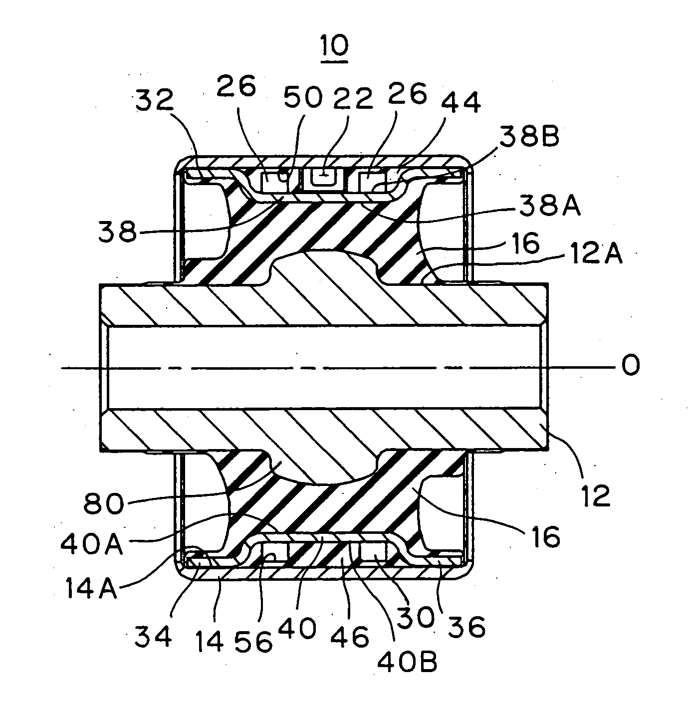
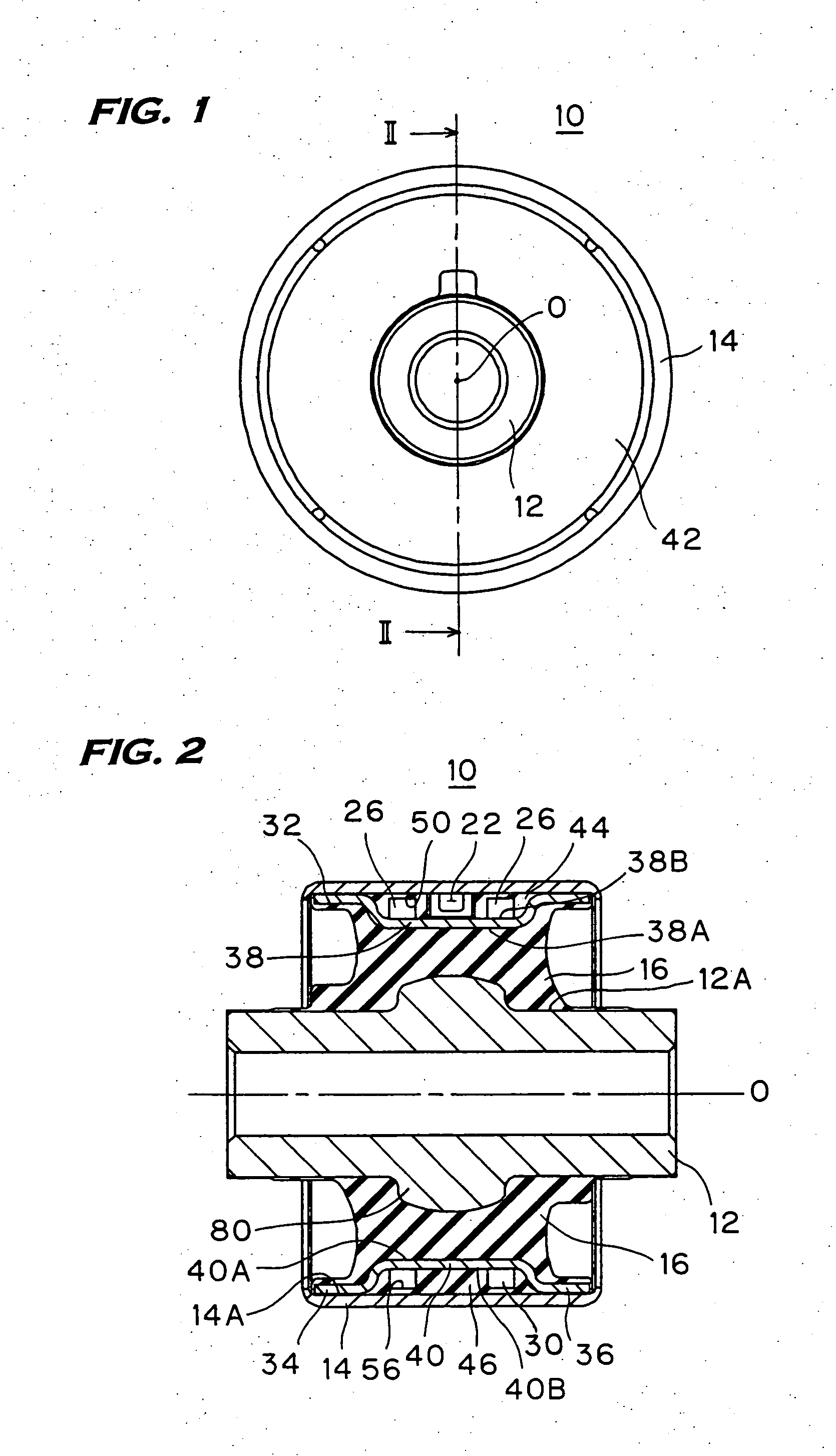
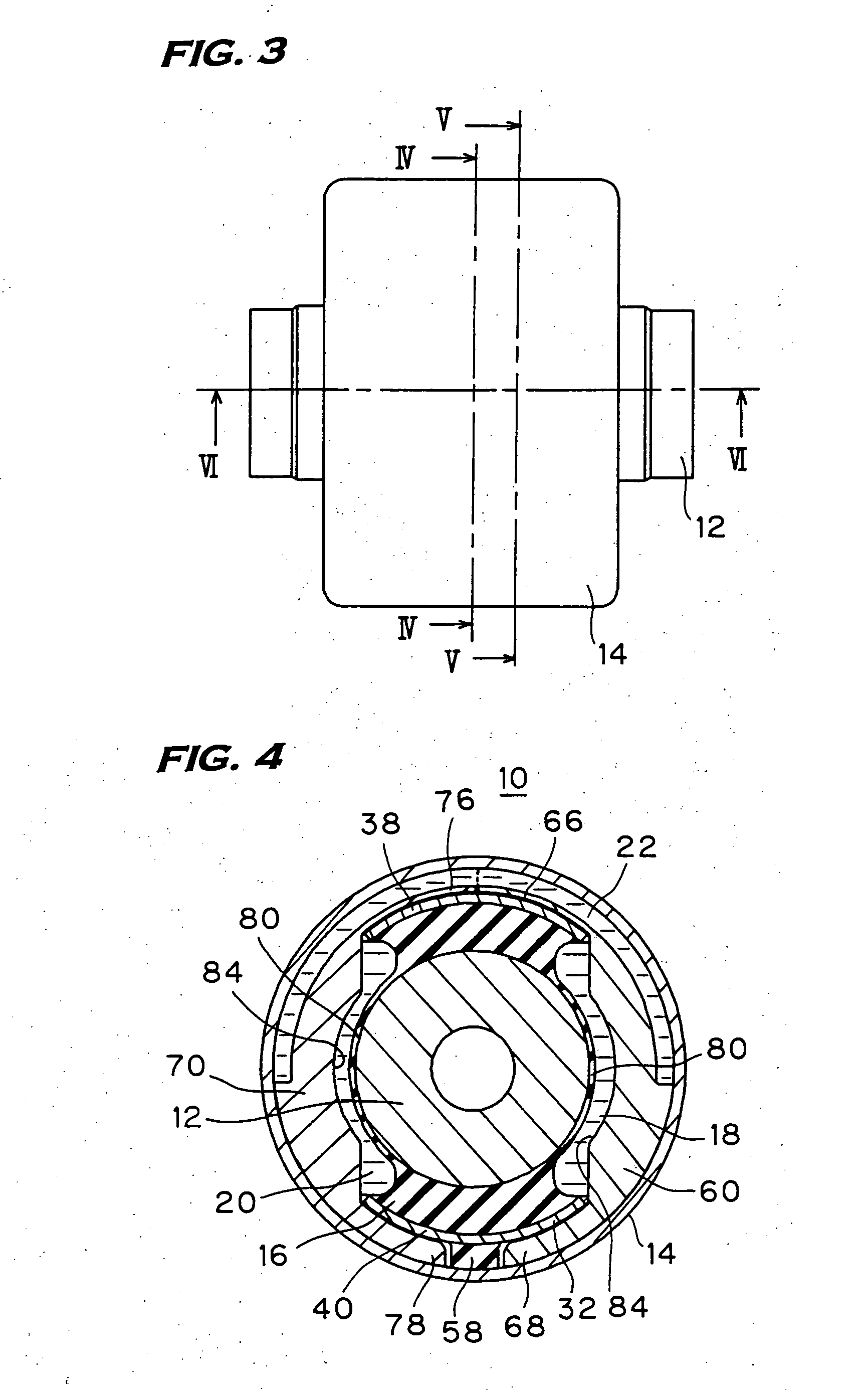
[0036]FIGS. 1 through 6 show a hydraulic vibration isolation device 10 relating to one embodiment of the invention. This hydraulic vibration isolation device 10 is a bushing type vibration isolator interconnecting a lower link 1 of a front wheel suspension of an automobile and a vehicle body frame as illustrated in FIG. 16. In FIG. 16, the reference numeral 16 designates a fire, and the reference numeral 3 designates a ball joint.

[0037] The hydraulic vibration isolation device 10 includes an inner cylinder 12 in a cylinder form to be connected to the vehicle body frame, an outer cylinder 14 in a cylinder form surrounding coaxially the inner cylinder 12 and to be press fitted in a press fitting hole of the lower link 1, and a vibration-isolating base body 16 made of rubber-like elastomer interposed between the former two.

[0038] Between the inner cylinder 12 and t...


PUM


Abstract

A hydraulic vibration isolator with sub-orifices having each rubber valve is provided, such that is aimed at ensuring a sufficient orifice length for a main orifice (22). An intermediate cylinder (32) disposed between an inner and an outer cylinders (12, 14) is comprised of fitting peripheral walls (34, 36) at both ends and joining walls (38, 40) between them; a first and a second liquid chambers (18, 20) are delimited by a vibration-isolating base body (16) interconnecting the joining walls and the inner cylinder; the fitting peripheral walls and the inner cylinder are interconnected by end walls (42) of rubber-like elastomer, and orifice-forming parts (44, 46) are provided on the outer surface sides of the joining walls. At the orifice-forming parts, a channel (50) having a first rubber valve (24) forming a first sub-orifice (26), a channel (56) having a second rubber valve (28) forming a second sub-orifice (30), and fitting recessed portions (48, 54) are provided. In the first and second liquid chambers, main orifice-forming members (60, 70) having respective channels (64, 74) on their outer peripheral surfaces are disposed, and fitting protrusions (66, 68, 76, 78) on both ends thereof are fitted in the fitting recessed portions, whereby the main orifice through which both liquid chambers communicate is formed.

Description

BACKGROUND OF THE INVENTION [0001] 1. Field of the Invention [0002] This invention relates to a hydraulic vibration isolation device and more particularly, to such a hydraulic vibration isolation device that abrupt hydraulic pressure fluctuation between two liquid chambers can be alleviated by flowing the liquid through by opening and dosing of orifices each equipped with a rubber valve. [0003] 2. Description of the Related Art [0004] For a hydraulic vibration isolation device of this type, WO 03 / 033936 A1 discloses the one which comprises an inner cylinder, an outer cylinder, a vibration-isolating base body made of rubber-like elastomer interposed between both cylinders, an intermediate cylinder, a first liquid chamber and a second liquid chamber provided to interpose the inner cylinder on both sides thereof, a main orifice bringing both liquid chambers into communication with each other, a first sub-orifice for flowing the liquid only from the first liquid chamber to the second li...

Claims


Application Information

Patent Timeline
Patent Type & Authority Applications(United States)
IPC IPC(8): F16F13/00
CPCF16F13/1472
Inventor KATO, AKIHIKOTOI, MASAYUKI
Owner TOYO TIRE & RUBBER CO LTD
Learn More