Rail based electric power generation system

a technology of electric power generation and rails, applied in the direction of fluid couplings, electric motor propulsion transmissions, vehicle energy devices, etc., can solve the problems of insufficient power generation cost-effective mechanism for power generation, and inability to provide cost-effective mechanisms for producing sufficient levels of power for operation of automated testing devices, etc., to facilitate the co-generation of power

Active Publication Date: 2006-06-08
GENERAL ELECTRIC CO
View PDF27 Cites 17 Cited by
  • Summary
  • Abstract
  • Description
  • Claims
  • Application Information

AI Technical Summary

Benefits of technology

[0005] In accordance with one exemplary embodiment, the present technique provides an electric power co-generation system for use with a railroad network. The system includes a power source, such as a power generation device or an external power source. The power co-generation system includes first and second electrical capacitance portions that are electrically coupled to the power source and that are configured to carry positive and negative charges, respectively. The power co-generation

Problems solved by technology

However, railroad networks often span thousands of miles and traverse through sparsely populated and remote regions.
Unfortunately, traditional automated devices generally obtain operating power from an external power source, which is not generally available in remote areas.
That is, the automated device receives operating power that is generated at a remote l

Method used


Image

  • Rail based electric power generation system
  • Rail based electric power generation system
  • Rail based electric power generation system

Examples


Embodiment Construction

[0015] As a preliminary matter, the definition of the term “or” for the purposes of the following discussion and the appended claims is intended to be an inclusive “or.” That is, the term “or” is not intended to differentiate between two mutually exclusive alternatives. Rather, the term “or” when employed as a conjunction between two elements is defined as including one element by itself, the other element itself, and combinations and permutations of the elements. For example, a discussion or recitation employing the terminology “‘A’ or ‘B’” includes: “A” by itself, “B” by itself, and any combination thereof, such as “AB” and / or “BA.”

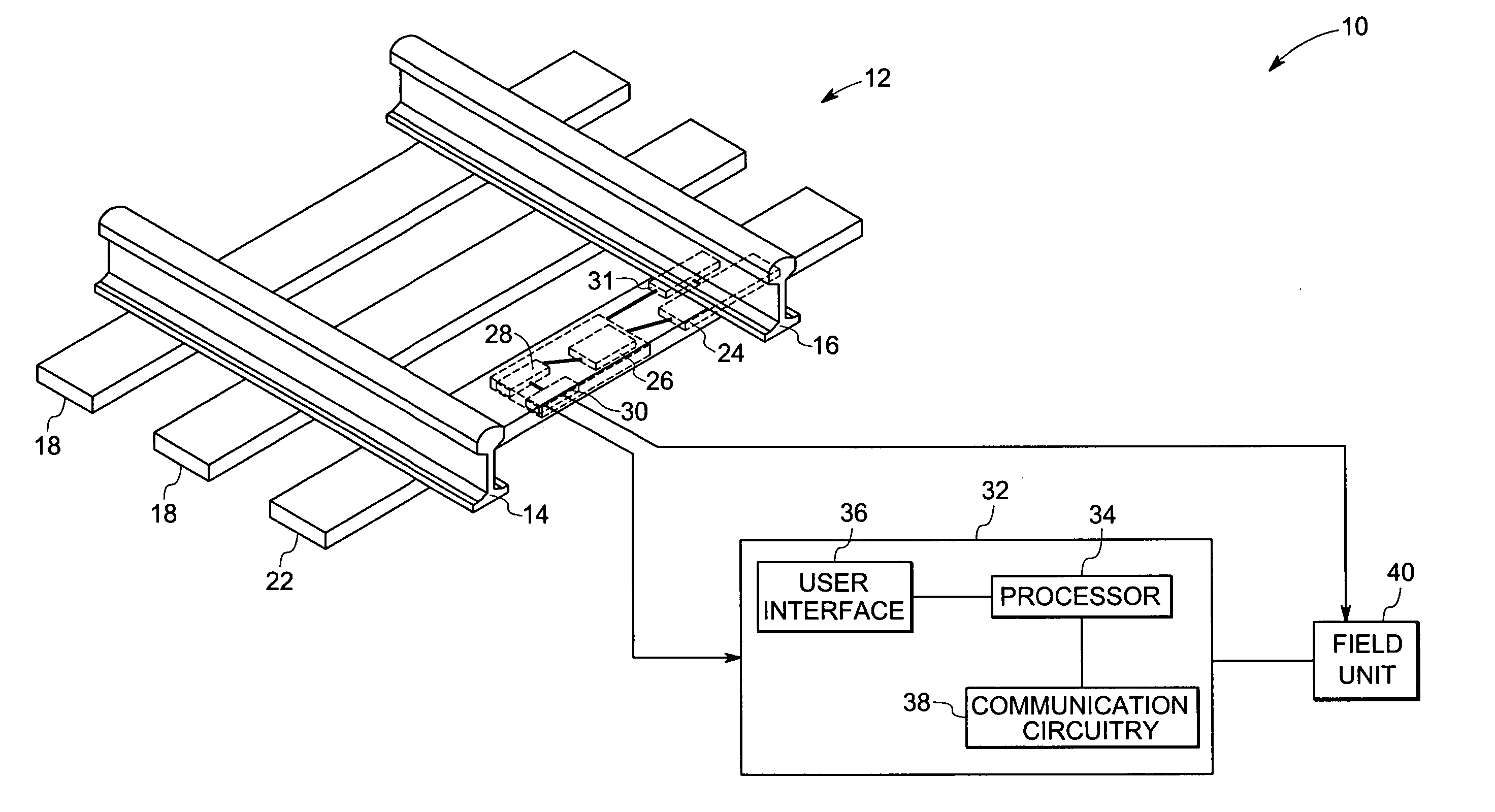
[0016]FIG. 1 illustrates an exemplary railway monitoring system 10. In the illustrated embodiment, the railway monitoring system 10 includes a railway track 12 that has a left rail 14, a right rail 16 and a plurality of ties 18 extending between and generally transverse to these rails 14, 16. The ties 18 are coupled to the rails 14, 16 and provide later...


PUM


Abstract

An electrical power generation system comprises a variable capacitor and a power source. The electrical power generation system is configured to generate electric power via movements of the rail. The power source is used in the form of a generator to prime the variable capacitor that effectively multiplies the priming energy of the power source by extracting energy from the passing vehicle. By alternately priming the variable capacitor using charge from the power source and discharging it at a later time in a cyclic manner to change the capacitance, a significantly large amount of electrical energy is produced due to change in capacitance than from the power source itself.

Description

BACKGROUND [0001] The present technique relates generally to rail based devices and, more specifically, to an energy co-generation device for generating electric power in response to vehicular traffic on a rail. [0002] Traditionally, operation data related to railroad traffic and railroad assets is gathered at manned junctions, such as a rail yard or a rail depot. By way of example, railroad workers often inspect rails for damage and loading conditions. As yet another example, railroad workers often inspect and inventory the incoming and outgoing railcars, to manage and facilitate the flow of traffic on a railroad network. However, railroad networks often span thousands of miles and traverse through sparsely populated and remote regions. [0003] Unfortunately, traditional automated devices generally obtain operating power from an external power source, which is not generally available in remote areas. That is, the automated device receives operating power that is generated at a remot...

Claims


Application Information

Patent Timeline
IPC IPC(8): H02K7/18F03G7/08F02B63/04
CPCH02N1/08F03G7/08
Inventor HERSHEY, JOHN ERIKWELLES, KENNETH BRAKELEY IISEELEY, CHARLES ERKLINDAVENPORT, DAVID MICHAELTOMLINSON, HAROLD WOODRUFF JR.FEIST, THOMAS PAUL
Owner GENERAL ELECTRIC CO
Why Eureka
Try Eureka