Parallax image pickup apparatus and image pickup method

a technology of image pickup and image, which is applied in the field of parallax image pickup apparatus and image pickup method, can solve the problems of difficult to obtain high resolution, difficult to obtain wide angle of view, and difficult to obtain accurate 3-dimensional localization information, and achieve the effect of improving the naturalness of the object size chang

Inactive Publication Date: 2006-06-08
SONY CORP
View PDF17 Cites 20 Cited by
  • Summary
  • Abstract
  • Description
  • Claims
  • Application Information

AI Technical Summary

Benefits of technology

[0039] Similarly, in the panning photographing system, a drawback in which, when the distance between the camera and the object changes, in the case of the same angle of view, the size of the object changes can be solved by the zooming process. Further, by optically executing the zooming, the problem of resolution deterioration is solved and in the case of monitoring the image in a real-time manner, the unnaturalness in which the size of the object changes is also improved.

Problems solved by technology

Although a commercially available lens such as a lens for 35 mm of a silver salt photograph or the like can be also used, in such a case, there is such a limitation that if the image pickup device is too large contrarily, it is difficult to obtain high resolution, and if it is too small, it is difficult to obtain a wide angle of view.
However, in the case of forming a plane hologram, the following drawbacks can be mentioned: it is necessary to correct a trapezoidal distortion; and more strictly speaking, a distortion which cannot be fully corrected remains later and it is difficult to obtain accurate 3-dimensional localization information.
Although the former trapezoidal distortion can be corrected by image processes, the latter is a perspective distortion which is caused in the case where although only the data obtained by photographing the object from the predetermined positions of the camera and the object is obtained, when the plane hologram is recorded, the image has to be constructed on the basis of information in which a distance between the hologram surface and the object is changed, that is, it is an uncorrectable distortion.
On the other hand, since the distance between the camera and the object changes, there is a drawback in which it is difficult to obtain an accurate focal point.
Although such a zooming process can be also executed by an image process after the photographing, since the unnecessary zoomed image which is not used is photographed, there is a problem of deterioration of the resolution.
In the case of monitoring the image in a real-time manner, there is also such a problem that unnaturalness in which the size of object changes remains.
In the case of using such a real-time monitor, there is a possibility that the framing becomes erroneous.
Since the camera is rotated while being moved on the straight rails, it is necessary to control at least the operations of two axes and it is complicated.

Method used


Image

  • Parallax image pickup apparatus and image pickup method
  • Parallax image pickup apparatus and image pickup method
  • Parallax image pickup apparatus and image pickup method

Examples


Embodiment Construction

[0056] An embodiment of the invention will be described in detail hereinbelow with reference to the drawings. The invention is not limited to the following example but arbitrary modifications are naturally possible within the scope of the invention without departing from the spirit of the invention.

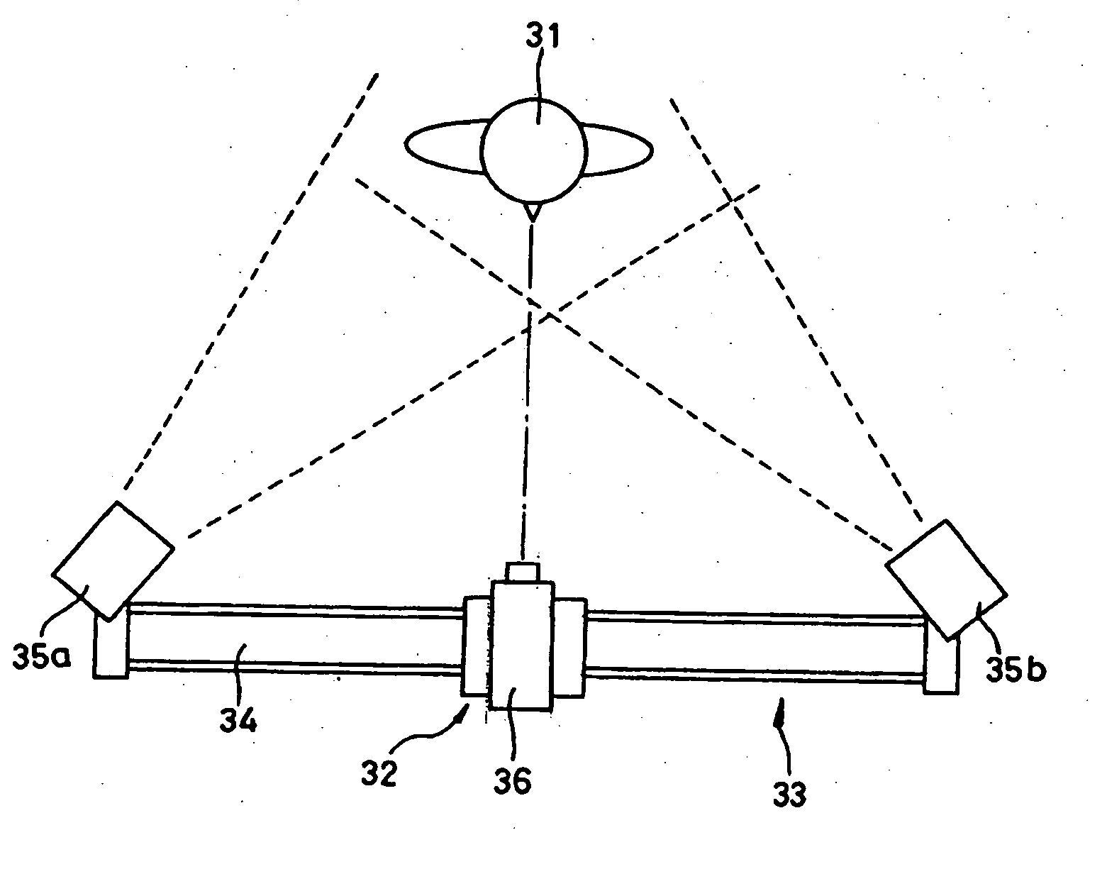
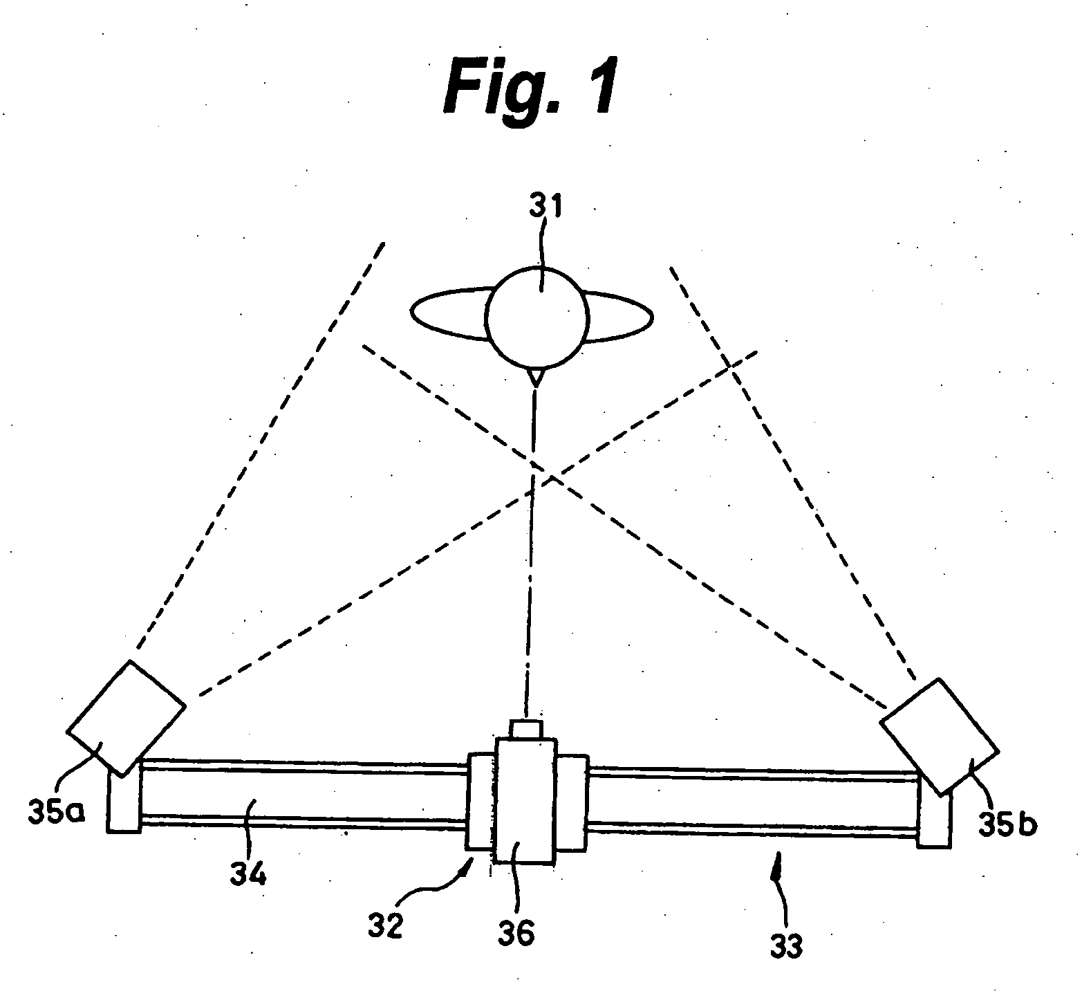
[0057]FIG. 1 shows a schematic construction of a parallax image pickup apparatus according to the embodiment of the invention. For easy understanding, it is assumed that the reference numerals common to those in FIG. 13 are used. The photographing unit 33 has the camera unit 32, camera unit feeding mechanism 34, and illuminating light sources 35a and 35b for illuminating the object 31 which is being photographed.

[0058] The camera unit 32 has, for example, the ⅔-inch CCD camera 36 for photographing a motion image. The camera unit 32 is put on the camera unit feeding mechanism 34 having a predetermined length, for example, a whole length of 3000 mm.

[0059] When the photographing is starte...


PUM


Abstract

A parallax image pickup apparatus for forming a parallax image train by photographing an object from a plurality of directions includes an image pickup unit in which an image pickup device and an image forming optical system are integrated in order to photograph the parallax images of the object; a rotating unit on which the image pickup unit is mounted and which rotates the image pickup unit in a parallax direction; an image pickup unit moving unit for rectilinearly moving the image pickup unit and the rotating unit synchronously with the rotation of the rotating unit; a control unit for controlling so that a virtual image pickup center portion is always located at the center of a photographed image; and a focal distance control unit for continuously changing a focal distance of the image pickup unit.

Description

CROSS-REFERENCE TO RELATED APPLICATIONS [0001] The present invention claims priority from Japanese Patent Application No. JP 2004-323448 filed on Nov. 8, 2004, the disclosure of which is hereby incorporated by reference herein. BACKGROUND OF THE INVENTION [0002] The invention relates to a parallax image pickup apparatus and an image pickup method which are applied to creation of, for example, a holographic stereogram. [0003] Two-dimensional images of an object which are obtained by seeing it from different visual points are used as original images and holograms to reproduce a three-dimensional image can be synthesized. A holographic stereogram is formed by, for example, a method whereby a number of images obtained by sequentially photographing an object from different observing points are used as original images and they are sequentially recorded as strip-shaped or dot-shaped element holograms onto a sheet of recording medium for a hologram. [0004] For example, as for a holographic ...

Claims


Application Information

Patent Timeline
Patent Type & Authority Applications(United States)
IPC IPC(8): H04N5/225
CPCH04N13/021G03B17/568G03B35/06G03B17/56H04N13/211
Inventor SHIRAKURA, AKIRA
Owner SONY CORP
Why Eureka
Try Eureka