Inverter circuit, fluorescent bulb operating device, backlight device, and liquid crystal display device

a technology of fluorescent bulbs and operating devices, which is applied in the direction of dc-ac conversion without reversal, instruments, lighting and heating apparatus, etc., can solve the problems of inability to stabilize the potential at both ends of the driven unit to reverse the phase relationship, the brightness at both ends cannot become constant, and the brightness at both ends cannot be constant, so as to achieve high image quality

Inactive Publication Date: 2006-06-08
SHARP KK
View PDF27 Cites 17 Cited by
  • Summary
  • Abstract
  • Description
  • Claims
  • Application Information

AI Technical Summary

Benefits of technology

[0020] According to any of the configurations of the above fluorescent tube lighting apparatus, it is possible to cancel out electrical or magnetic noise generated in a core or the like by a transformer induction effect inside each inverter circuit, making it possible to eliminate noise generated at the two ends of a driven unit.
[0036] By employing such configurations, since uniform planar luminescence is provided from the backlight apparatus, the brightness over the entire display screen can be equalized, and based thereon a liquid crystal display having high image quality can be provided.

Problems solved by technology

Accordingly, a problem arises whereby potential at both ends of the driven unit cannot be stabilized to reverse the phase relationship thereof.
However, when a fluorescent tube is lit using the above conventional art, the phases at both ends do not stabilize and the phase relationship cannot be reversed, and as mentioned above, a problem thus arises that brightness at both ends does not become constant.
However, when driving a backlight using the conventional art, since it is not possible to stabilize the voltages at both ends of a fluorescent tube to reverse the phase relationship thereof, the brightness at both end sides does not become constant and it is difficult to obtain uniform brightness across the entire display.
However, a problem exists whereby it is difficult to provide fine image quality unless the brightness of a backlight employed as the light source of the liquid crystal display is constant over the entire display.

Method used


Image

  • Inverter circuit, fluorescent bulb operating device, backlight device, and liquid crystal display device
  • Inverter circuit, fluorescent bulb operating device, backlight device, and liquid crystal display device
  • Inverter circuit, fluorescent bulb operating device, backlight device, and liquid crystal display device

Examples


first embodiment

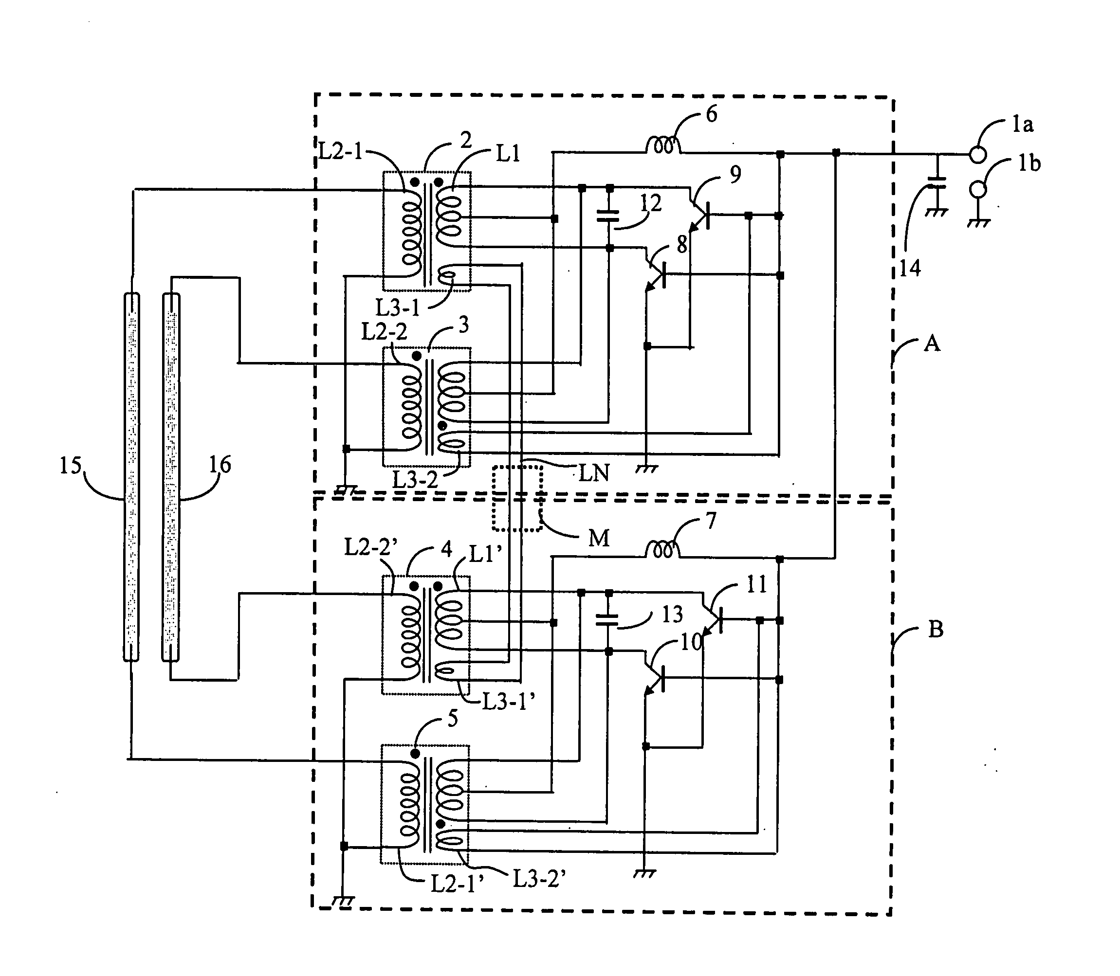
[0054] First, a fluorescent tube lighting apparatus according to the present invention will be described referring to FIGS. 1(a) to 1(e). FIG. 1(a) illustrates an example of the circuitry of the principal part of the fluorescent tube lighting apparatus according to the present embodiment. As shown in FIG. 1(a), inverter circuits A and B are configured with two inverter transformers 2 and 5, or 3 and 4 as one set, and are respectively provided at the two ends of two fluorescent tubes 15 and 16 as driven units. The circuitry comprises a configuration (LN) whereby, of the inverter transformers 2 and 5, or 3 and 4 that are respectively connected to the two ends of fluorescent tube 15 or 16, the two ends of feedback windings of the step-up transformers not used in self-excited oscillation are connected to each other.

[0055] The principal components of the apparatus shown in FIG. 1(a) are two inverter circuits A and B, and two fluorescent tubes 15 and 16. Further, inverter circuits A and B...

second embodiment

[0084] Next, a fluorescent tube lighting apparatus according to the present invention will be described referring to FIGS. 2(a) to 2(d).

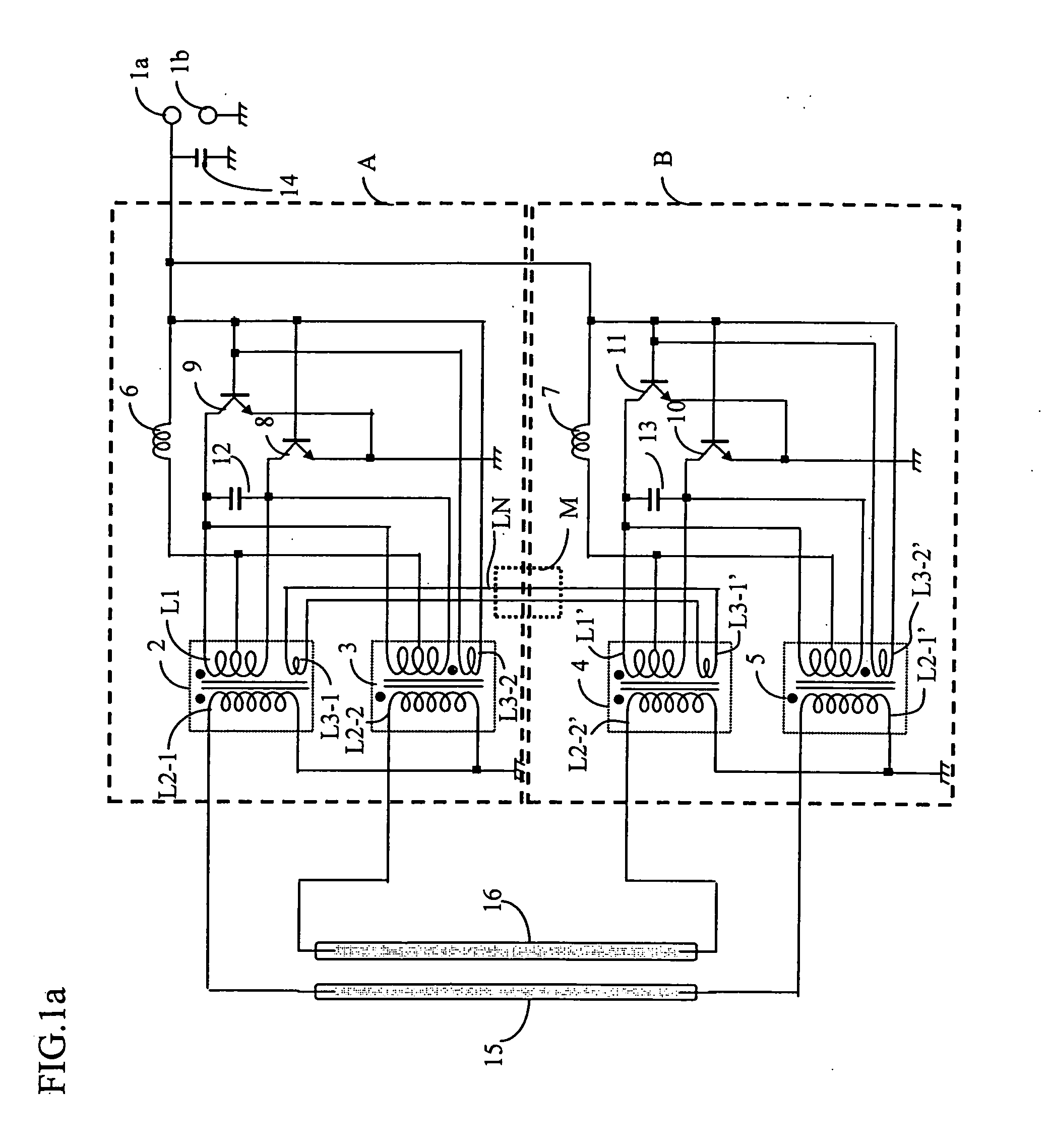
[0085]FIG. 2(a) shows the principal circuit diagram of the second embodiment of the fluorescent tube lighting apparatus of the present invention. The transformers employed in the inverter transformers are 2-in-1 transformers, and in order to apply voltages of opposite phases relative to each other to the two ends of the fluorescent tubes, the two ends of the tubes are respectively connected to one end of an inverter transformer. Furthermore, with respect to the tertiary winding used in self-excited oscillation of each inverter circuit, by connecting the windings to each other by means of coils or the like respectively provided in parallel, the two inverter circuits are indirectly connected.

[0086] The principal components of FIG. 2(a) are two inverter circuits A and B and fluorescent tubes 15 and 16. Inverter circuits A and B comprise a direct curre...

third embodiment

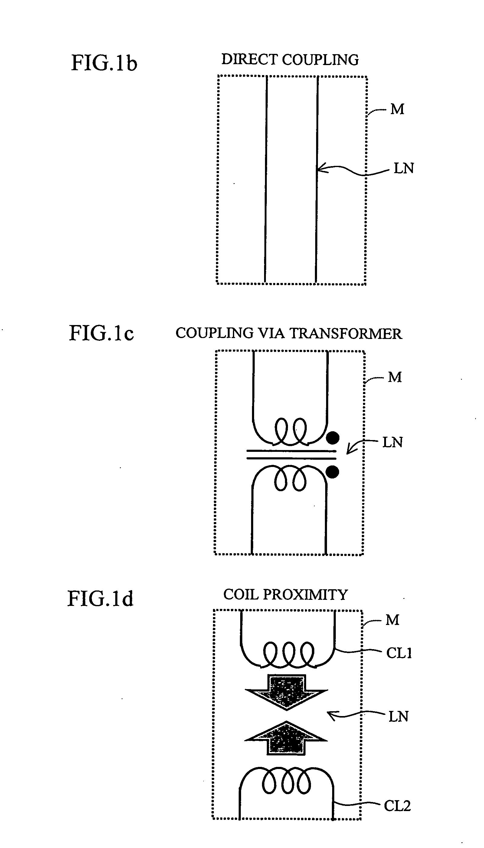
[0091] Next, a fluorescent tube lighting apparatus according to the present invention will be explained referring to the drawings. FIG. 3(a) illustrates an example of the configuration of the fluorescent tube lighting apparatus according to the present embodiment. The configuration shown in FIG. 3(a) is characterized by having, as a means for synchronization of two inverter circuits A and B, a first configuration wherein choke coils (not shown in the figure) provided between input terminal 1a and each of center taps CT1 and CT2 tapped from each of primary windings L1 and L1′ are indirectly connected together and the indirect connection is configured so that inverters A and B are driven in opposite phase relative to each other, and a second configuration wherein secondary windings L2-1 and L2-1′, and L2-2 and L2-2′ within inverter circuits A and B are respectively wound in reverse with respect to each other. Thus, the magnetic fields of the cores are cancelled out.

[0092] By comprisin...


PUM


Abstract

A driving apparatus and a driving method are disclosed that are capable of uniformly lighting each entire fluorescent tube irrespective of the length or number of fluorescent tubes when simultaneously driving a plurality of fluorescent tubes in a fluorescent tube lighting apparatus. When two inverter circuits having respective transformers are provided at both ends of a fluorescent tube to light the fluorescent tube by push-pull driving, feedback windings of transformers not used in self-excited oscillation of each inverter circuit are connected together, with the transformer connection that connects together the feedback windings being either in-phase or in opposite phase, and the method of connection for fluorescent tubes connecting to secondary windings of each transformer can be changed in accordance with that connection method.

Description

TECHNICAL FIELD [0001] The present invention relates to an inverter circuit driving a driven unit, a fluorescent tube lighting apparatus driving a fluorescent tube, a backlight apparatus supplying uniform planar light using a fluorescent tube driving apparatus, and a liquid crystal display that can display an image by assigning gradation levels to light emitted from the backlight apparatus using a liquid crystal panel. BACKGROUND ART [0002] Japan Utility Model Publication (Unexamined Application) No. 5-90897 discloses the following art as a conventional example of an inverter circuit driving a driven unit using two step-up transformers. [0003] That is, as shown in FIG. 13, the conventional example describes an inverter circuit 308 comprising: an inverter circuit 304a having a step-up transformer 301a having a primary winding 309a, a secondary winding 305a and a feedback winding 306, and a pair of transistors 302a and 303a for push-pull driving; and another inverter circuit 304b havi...

Claims


Application Information

Patent Timeline
IPC IPC(8): F21V7/04H05B41/282
CPCG09G3/3406Y02B20/185H05B41/2822H05B41/2821Y02B20/00G02F1/133H05B41/24H02M7/483
Inventor INOUE, YUTAKASHIMIZU, MASAKIOHTANI, SHUHKI
Owner SHARP KK
Why Eureka
Try Eureka