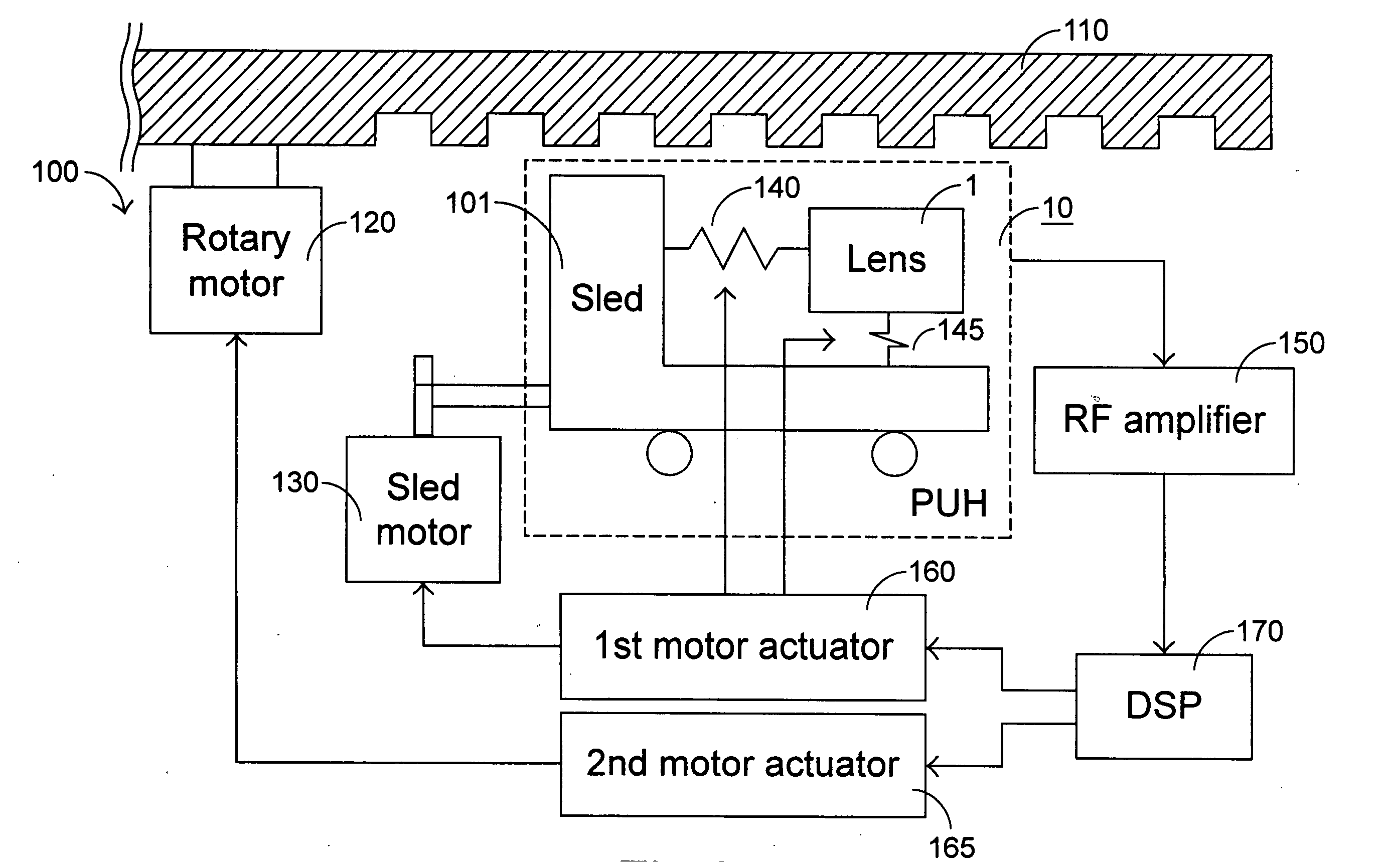
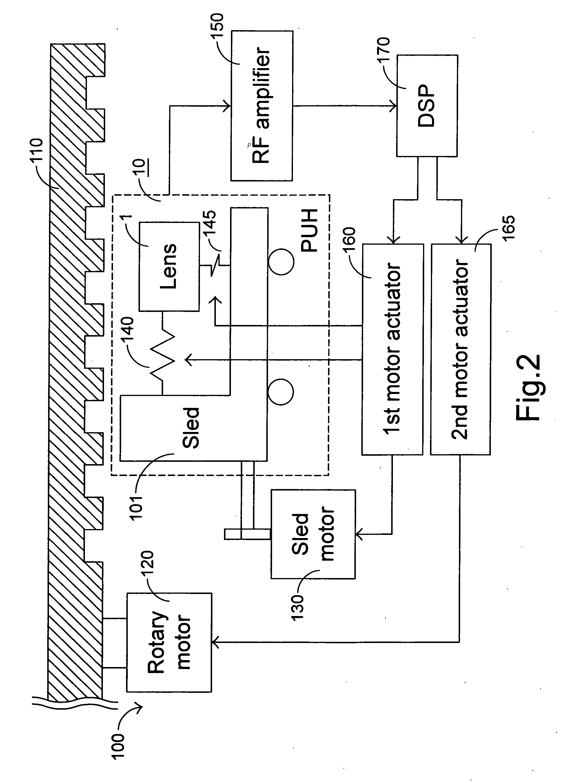
[0017] Please refer to FIG. 2. The optical recording/reproducing apparatus 100 includes an optical pickup head (PUH) 10 that is moved by a sled motor 130 and finely tuned with a tracking coil 140 in the tracking direction. In addition, the PUH 10 is moved in the focusing direction with a focusing coil 145. After the sled 101 of the PUH 10 is moved for a seeking operation by the sled motor 130, the lens 102 of the PUH is shifted with the tracking coil 140 and the focusing coil 145 for tracking and focusing operations.
[0018] For well tracking and addressing in a writing procedure, a feedback tracking mechanism is implemented. That is, the PUH 10 reads wobbles from the optical disc 110 so as to generate a wobble signal, and then a radio-frequency (RF) amplifier 150 generates a radio-frequency (RF) signal, a tracking error (TE) signal and a focusing error (FE) signal in response to the wobble signal. The RF, TE and FE signals are then inputted into and processed by a digital signal processor (DSP) 170 so as to result in a plurality of actuating signals. For example, the DSP 170 outputs three actuating signals to a first motor actuator 160 in response to the TE signal and the FE signal to control the movement of the sled motor 130, tracking coil 140 and focusing coil 145 so that the PUH 10 can precisely locate the target track and focus on the target point. An additional actuating signal is outputted to a second motor actuator 165 by the DSP 170 to control the rotary motor 120 so that the optical disc 110 can be rotated at a proper speed. According to the feedback tracking mechanism, the levels of the TE signal and the FE signal are supposed to be approximately zero. However, due to some unexpected problems like bad disc dyeing, disc distortion, scratch or dirt, the wobble signal may become unreliable and result in undesired drifts of TE and FE signals. Consequently, the actuating signals would be unable to move respective elements to proper positions.
[0019] In order to solve these problems, the present invention monitors the TE and FE signals generated in response to the wobble signal in the feedback tracking writing procedure. According to the updated TE and FE signals, the rotating speed of the optical disc is properly adjusted. If the levels of the TE signal and/or FE signal change to a large extent within a preset period, the rotating speed of the optical disc has to keep at a low speed. On the other hand, if the levels of the TE signal and/or FE signal keep stable for a long term, the rotating speed of the optical disc can be increased. The increase in the rotating speed of the optical disc can be done in several stages, as shown in FIG. 3.
[0020]FIG. 4 is an exemplified flowchart of a speed control method of the present invention. The speed control method will be described hereinafter with reference to FIG. 3 as well. As exemplified by the stages of FIG. 3, there are four rotating speeds available for the optical recording/reproducing apparatus, e.g. 2×, 4×, 6× and 8×. In general but not necessarily, the optical recording/reproducing apparatus starts working at a minimal rotating speed, e.g. 2×. Meanwhile, the TE and FE signals are generated in a feedback mode and sampled periodically. For each rotating speed, respective threshold levels for determining whether the TE and FE signals are stable are preset for the TE signal and the FE signal. For example, on the condition that the optical disc is operated at a rotating speed of 2×, the threshold levels preset for the TE and FE signals are both 0.4 volts. If the counts of the TE and FE signals exceeding their threshold levels within preset periods of time are limited, i.e. less than preset numbers, the optical recording/reproducing apparatus can be considered operating well together with the PUH so that the rotating speed of optical disc can be increased to a higher level for example 4×. Otherwise, the rotating speed will keep at 2×. Then, the counts can be zeroed. On the condition that the optical disc is operated at a rotating speed of 4×, the threshold levels for the TE and FE signals are up-shifted to both 0.5 volts. The TE and FE signals exceeding their current-stage threshold levels are counted and compared with the preset count threshold in a similar way described above so as to determine whether the rotating speed should be increased or not. Likewise, the threshold levels 0.6 volts are used to discriminate the TE and FE signals when the optical disc is operated at a rotating speed of 6×.
[0021] As far as the comparison of the counts of the TE and FE signals exceeding their threshold levels within preset periods of time with the preset numbers is concerned, a variety of criteria can be applied. For example, the rotating speed of the optical disc can be increased as long as one of the signals TE and FE keep stable. That is, the count of the TE signal exceeding the TE threshold level is less than a corresponding preset number or the count of the FE signal exceeding the FE threshold level is less than another preset number corresponding thereto. Alternatively, the rotating speed of the optical disc cannot be increased unless the count of the TE signal exceeding the TE threshold level is less than a corresponding preset number and the count of the FE signal exceeding the FE threshold level is less than another corresponding preset number. In a further example, the count of the TE signal exceeding the TE threshold level and the count of the FE signal exceeding the FE threshold level are subjected to a mathematic operation so as to control the rotating speed of the optical disc. For example, the count of the TE signal exceeding the TE threshold level is added to the count of the FE signal exceeding the FE threshold level, and the rotating speed of the optical disc is increased when the sum is less than a preset number.
[0022] By using the present invention, the rotating speed of the optical disc in the writing procedure can be well controlled so as to result in more precise TE and FE signals in the feedback tracking mechanism. As a result, the reliability of the data written into the optical disc can be improved.
[0023] While the invention has been described in terms of what is presently considered to be the most practical and preferred embodiments, it is to be understood that the invention needs not be limited to the disclosed embodiment. On the contrary, it is intended to cover various modifications and similar arrangements included within the spirit and scope of the appended claims which are to be accorded with the broadest interpretation so as to encompass all such modifications and similar structures.