Node redundancy method, interface card, interface device, node device, and packet ring network system

a node and network system technology, applied in data switching networks, frequency-division multiplexes, instruments, etc., can solve the problems of telecommunications operators and the like not being able to meet the requirement of high-speed switching with the time of 50 milliseconds or below, and the number of optical fibers being disadvantageously required to be installed anew,

Inactive Publication Date: 2006-06-08
FUJITSU LTD
View PDF7 Cites 52 Cited by
  • Summary
  • Abstract
  • Description
  • Claims
  • Application Information

AI Technical Summary

Benefits of technology

[0023] It is an object of the present invention to at l

Problems solved by technology

In the conventional technology, when node redundancy is realized with a mesh-formed or a tree-type network, a number of optical fibers are disadvantageously required to be installed anew for connecting the node devices to the redundant node devices.
With the redundant node configuration using the STP, about one minute is required for switching to a bypass route when line trouble or node trouble occurs, and the requirement of telecom

Method used


Image

  • Node redundancy method, interface card, interface device, node device, and packet ring network system
  • Node redundancy method, interface card, interface device, node device, and packet ring network system
  • Node redundancy method, interface card, interface device, node device, and packet ring network system

Examples


first embodiment

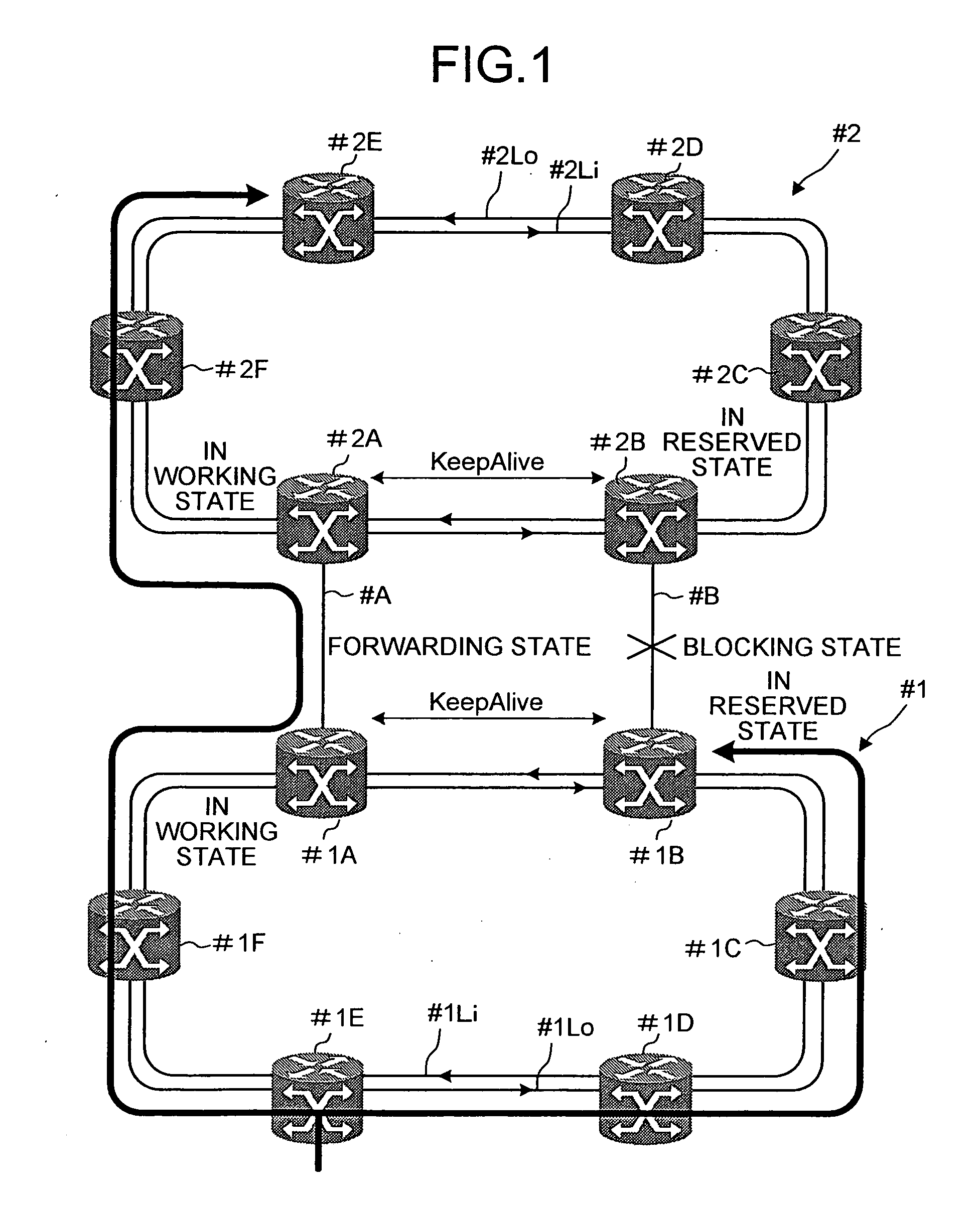
[0066]FIG. 1 is a schematic for explaining the outline of a network according to the present invention. The network includes a RPR network #1 and a RPR network #2 connected to each other with node redundancy.

[0067] The redundant node device also means a redundant node. Moreover, a node device also means a node.

[0068] The RPR network #1 includes a redundant node device #1A, a redundant node device #1B, and node devices #1C to #1F connected to each other in a ring form with an inner loop communication path #1Li and an outer loop communication path #1Lo for bilateral communications. Thus, the RPR network #1 has the dual ring configuration. As a result, even if trouble occurs in one ring, communications can be continued via other ring.

[0069] The RPR network #2 includes a redundant node device #2A, a redundant node device #2B, and node devices #2C to #2F connected to each other in a ring form with an inner loop communication path #2Li and an outer loop communication path #2Lo for bilat...

second embodiment

[0207] In the second embodiment, in addition to (1) priority, (2) common address, and (3) redundant state, (4) redundant group ID is added to a PDU of the keep-alive packet shown in FIG. 7. The redundancy group ID (4) is set to the default state, like other parameters, after power is turned ON, or after resetting.

[0208] As described above, in the second embodiment, by adding a redundancy group ID, a group of redundant node devices in an RPR network is more clarified.

[0209] Although it is possible to differentiate redundancy groups without adding a redundancy group ID to a keep-alive packet because redundancy groups have different common addresses respectively, and in the second embodiment, also a redundancy group ID is added to a keep-alive packet fur the purpose to prepare a ring topology table with higher reliability.

[0210] Further, in the second embodiment, the ring topology table shown in FIG. 17 is used in place of the ring topology table shown in FIG. 9. In the ring topology...

third embodiment

[0220] In the third embodiment, information on a plurality of redundancy groups is set in a PDU in a keep-alive packet shown in FIG. 7.

[0221] In the case of the redundant node device #11D, information on both the redundancy group with the ID set to 1 and the redundancy group with the ID set to 2 is set in a keep-alive packet, and the keep-alive packet is broadcast-delivered to the RPR network #11.

[0222] With this operation, each redundant node device and each node device having received the keep-alive packet prepare a ring topology table shown in FIG. 19.


PUM


Abstract

A network includes a plurality of redundant nodes and ordinary nodes. A first redundant node from among the redundant nodes sets a common address and setting information in a message packet and broadcasts the message packet over the network. The common address is commonly used by all the redundant nodes on the network. The setting information is indicative of the fact that the first redundant node is a redundant node. All the nodes have a topology table. The nodes that receive the message packet set in their topology table information indicating of presence of the first redundant node and the common address shared by the redundant nodes. When transmitting a packet to the first redundant node, a node sets the common address as a destination address of the packet.

Description

BACKGROUND OF THE INVENTION [0001] 1. Field of the Invention [0002] The present invention relates to a node redundancy method, an interface card, an interface device, a node device, and a packet ring network system used in networks. [0003] 2. Description of the Related Art [0004] Recently, there has been a remarkable increase in data traffics over the Internet mainly based on the Ethernet (Registered trade name) or IP (Internet Protocol) packets, rapid increase in ADSL (Asymmetric Digital Subscriber Line) users, and advent of VoIP (Voice over IP) technique. As a result, a network of packet rings (described as a packet ring network or simply, as a ring hereinafter), in which packets are directly processed on the ring network for band management for each packet or for statistic multieffect, has attracted attention as a potential alternative for a ring network based on the conventional SONET / SDH (Synchronous Optical Network / Synchronous Digital Hierarchy) devices. [0005] Especially, the...

Claims


Application Information

Patent Timeline
IPC IPC(8): H04J3/14H04L12/42H04L12/437
CPCH04J3/14H04L12/437H04L45/12H04L45/586
Inventor MITSUMORI, YASUYUKI
Owner FUJITSU LTD
Why Eureka
Try Eureka