

Mobile-terminal-oriental transmission method and apparatus
- Summary
- Abstract
- Description
- Claims
- Application Information
AI Technical Summary
Benefits of technology
Problems solved by technology
Method used
Image

Examples
embodiment 1
[0070] Embodiments of a transmission method according to the present invention are described below with reference to the accompanying figures with application to zapping used by way of example.
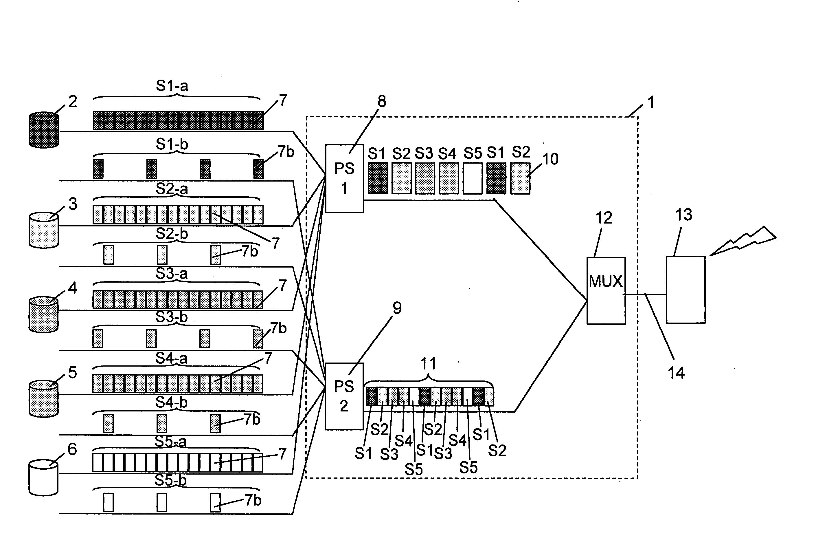
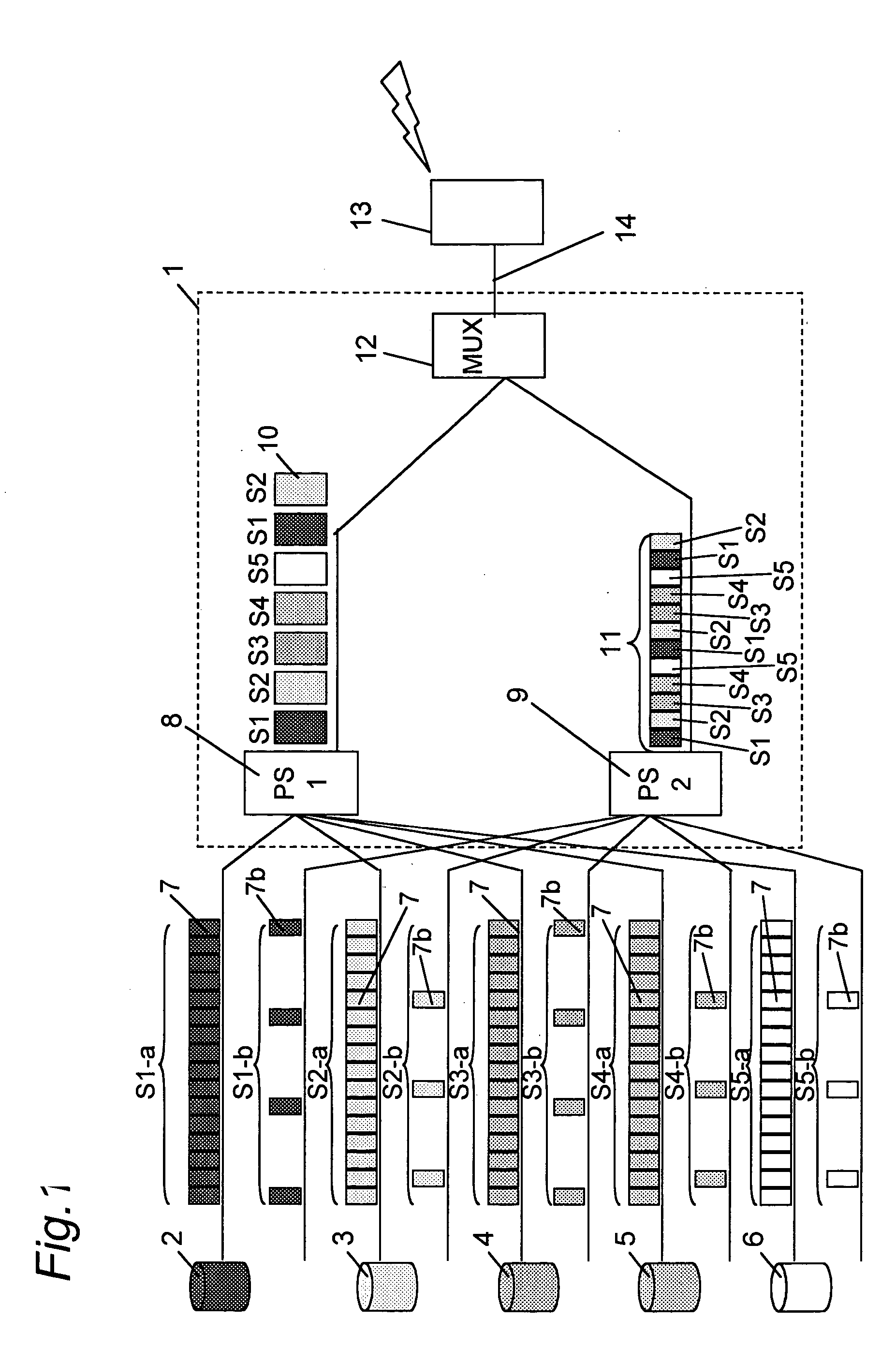
[0071]FIG. 1 describes generating a transmission signal in the present invention.
[0072] Reference numeral 1 is a digital broadcasting head end, and 2, 3, 4, 5, 6 are the content sources for services S1, S2, S3, S4, S5. The content of each service is encoded in both high quality and low quality, resulting in high quality IP (Internet Protocol) package 7, and low quality IP packet 7b. Each content source has a high quality encoder for generating IP packets 7, and a low quality encoder for generating IP packets 7b, each encoder being a discrete real-time encoder. The high quality encoder has an internal clock CLa indicating real time, and the low quality encoder has an internal clock CLb indicating real time. That the time kept by internal clock CLa and the time kept by internal clock CLb match...
embodiment 2
[0131] Another embodiment of the transmission method of the present invention is described with reference to FIG. 8.
[0132]FIG. 8 describes transmission signal generation in the present invention. FIG. 8 differs from FIG. 1 in that the output of the processor 9 is input to the processor 8 instead of multiplexer 12, and a buffer B6 is added to the processor 8.
[0133] An approximately 5 minute portion of the low quality TS packet stream 11 output from the processor 9 is stored to buffer 6, and output from the processor 8 as a single burst 15. It goes without saying that burst 15 contains zapping TS packet group S0, which is equivalent to the l1 TS packet stream 11 to which the same PID address is added.
[0134] Time information denoting the timing at which the corresponding high quality burst is transmitted is added to the section containing the zapping burst 15. The multiple bursts 10 and zapping burst 15 are transmitted sequentially in bursts to the multiplexer 12, and are multiplexe...
embodiment 3
[0148] Transmitting zapping data in bursts
(Transmitting Still Images and Audio)
[0149] This third embodiment of the invention improves upon zapping data transmission in the first embodiment, and is described with reference to FIG. 12 and FIG. 13.
[0150]FIG. 12 shows the data allocation on the transmission channel 14 in this embodiment of the invention.
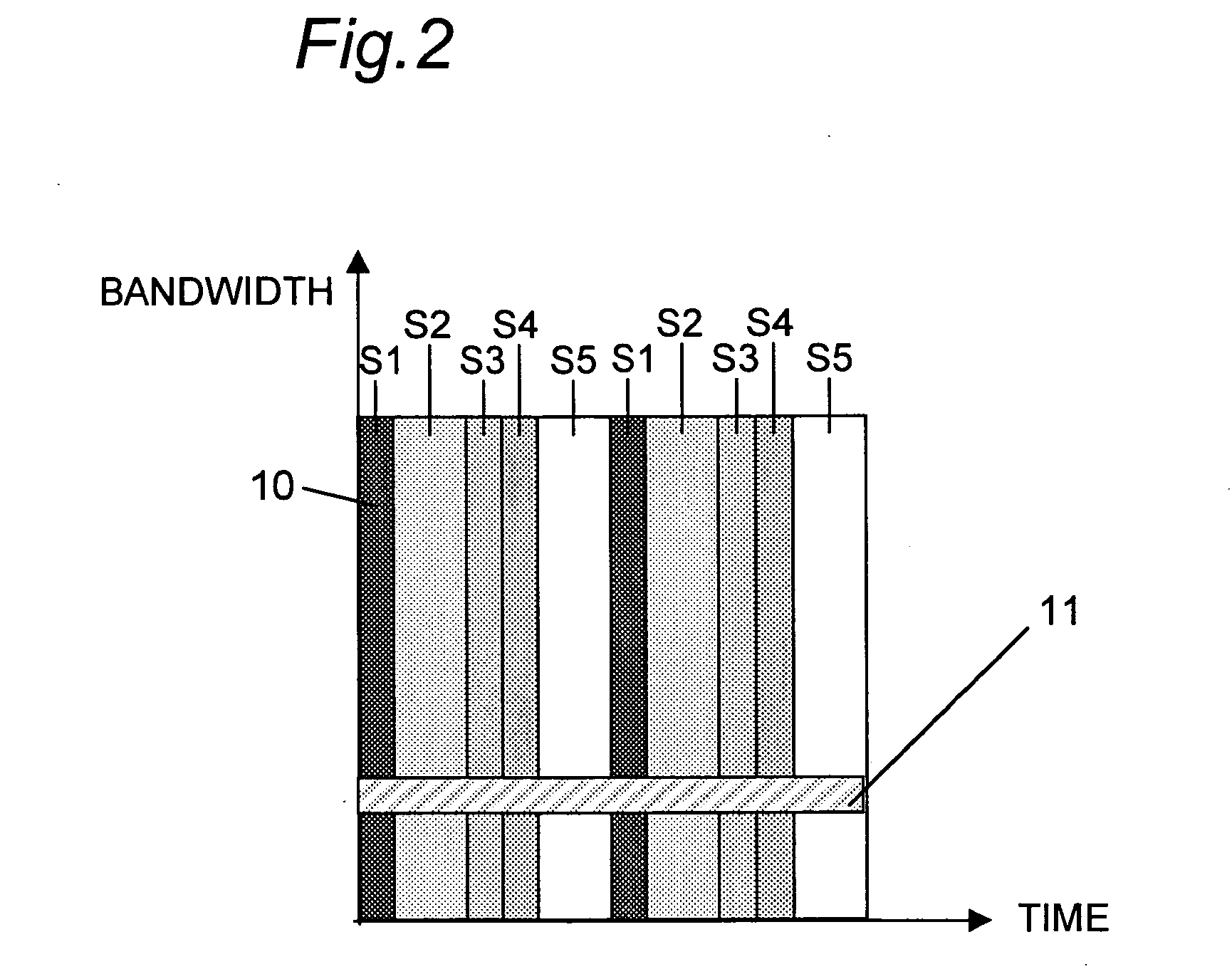
[0151]FIG. 7 shows the data allocation on the transmission channel 14. Reference numeral 10 in FIG. 7 denotes a time slice carrying high quality data for services 1 to 5 with the video and audio data compressed using MPEG-4 to a 350-kbps average transfer rate. Reference numerals 11s1, 11s2, 11s3, 11s4, 11s5 denote low quality data for zapping. Packages are transmitted containing approximately 10 kbyte of still image data representing the video transmitted in each time slice of each service, and approximately 25 seconds of audio data containing the audio transmitted in one time slice of high quality data compressed to approximately 8...
PUM
 Abstract
Description
Claims
Application Information