Intramedullary nail

a technology of intramedullary nail and nail, which is applied in the field of intramedullary nail, can solve the problems of affecting the accuracy of surgical procedures, so as to prevent the tip of the wire from being blunted, and the surgical procedure is quick and yet highly reliable.

Inactive Publication Date: 2006-06-08
TANDON VINEET DEV
View PDF3 Cites 15 Cited by
  • Summary
  • Abstract
  • Description
  • Claims
  • Application Information

AI Technical Summary

Benefits of technology

[0014] Nails according to the invention provide significant advantages over known nails in that their use allows for a quicker and yet highly reliable surgical procedure. A nail of the invention is insertable into the medullary cavity of a bone in a conventional manner. By use of a jig attached to the proximal end of the nail, a leading end of a flexible elongate wire which carries a cutting or grinding tip is accurately guided to the outside of the bone overlying one of the proximal lateral apertures of the nail, and is used to produce a hole in the bone at that position. Alternatively, to prevent blunting of the tip of this wire, the hole drilled through the bone adjacent to the proximal lateral aperture in the nail may be made with a drill guided by a jig. The wire is then inserted through the aperture and passed down the cavity, guided by the relevant guide means provided therein, or else is pass

Problems solved by technology

However, drilling apertures near the distal end of the bone is problematic.
The path of the nail is often slightly distorted as it passes down the medulla and across the fracture and only a minor degree of angulation or rotation of the nail makes the use of a jig inaccurate such that it will not align the hole for the screw or bolt accurately with the aperture near the distal end of the n

Method used


Image

  • Intramedullary nail
  • Intramedullary nail
  • Intramedullary nail

Examples


Embodiment Construction

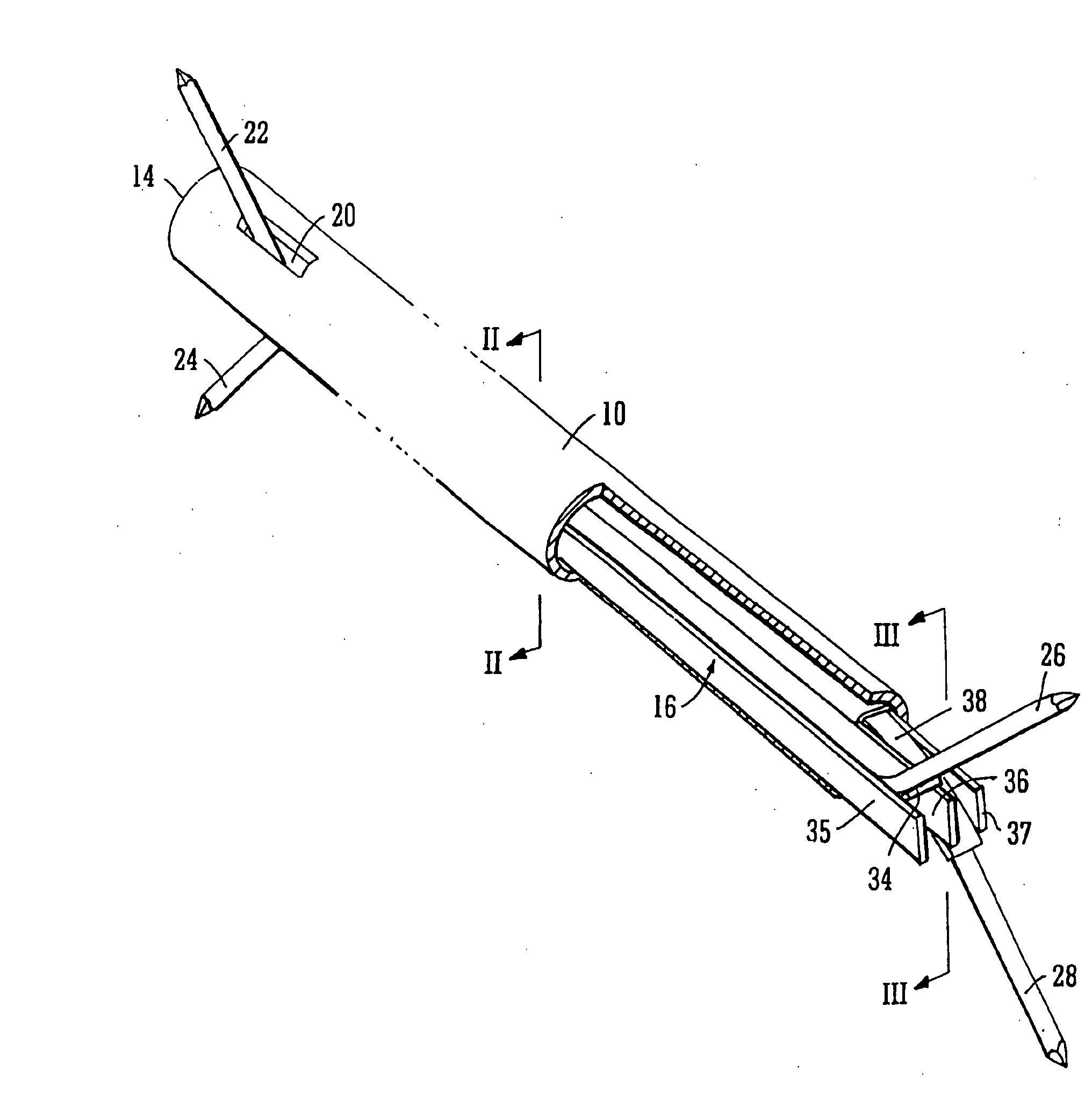
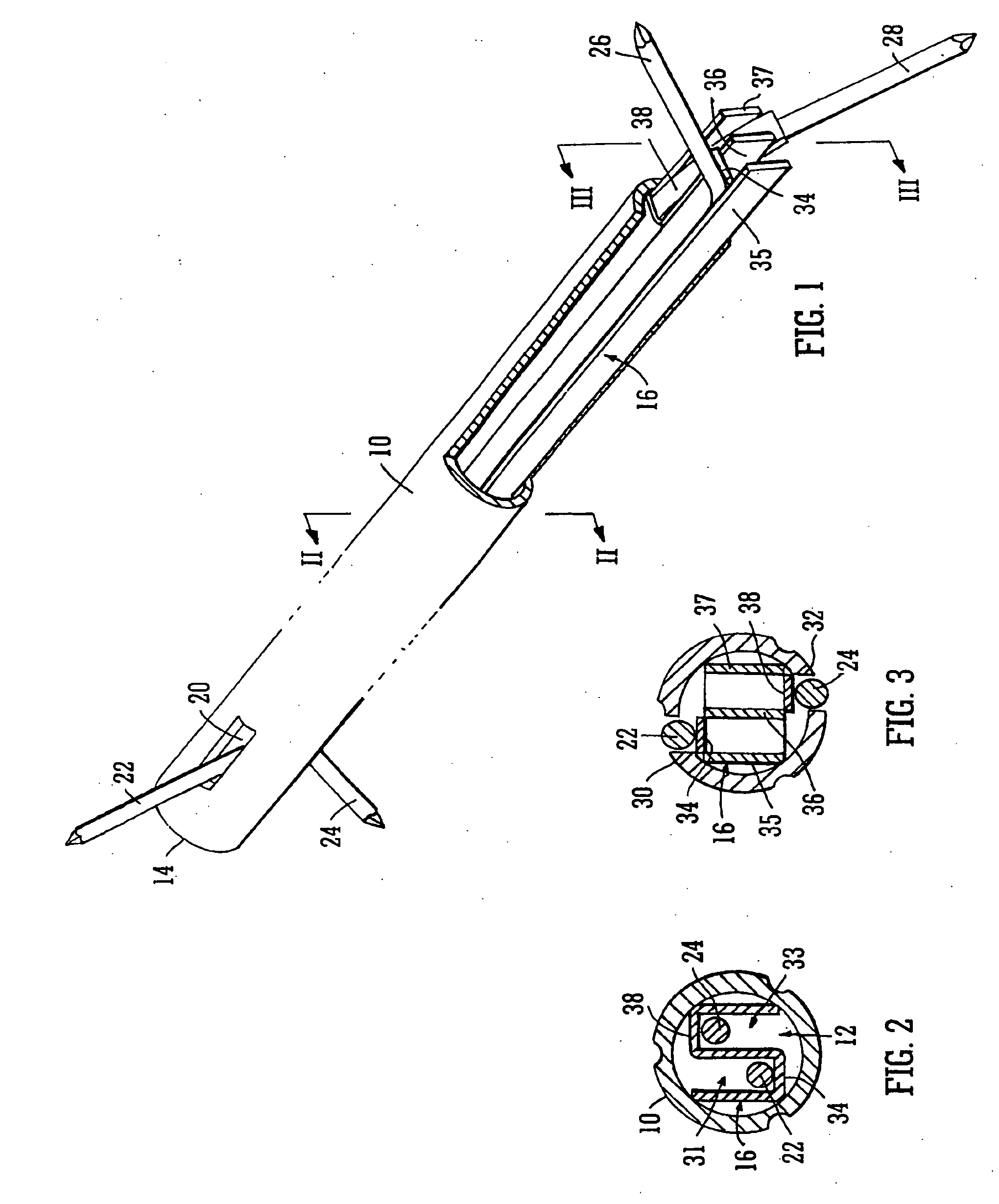
[0034] Referring firstly to FIGS. 1 to 3, a first practical embodiment of an intramedullary nail of the invention comprises an elongate rod 10 of stainless steel or titanium having a cavity 12 therethrough. Thus, it is hollow throughout. It has a first end 14, which may be termed a proximal end, and a second end, which may be referred to as a tip or distal end, although the latter is not shown in the drawings owing to the portion cut away to show the interior of the cavity 12. The rod 10 may taper from its proximal end to its tip, although again that is not shown in the drawings.

[0035] Two apertures, termed proximal lateral apertures, are formed in the wall of the rod 10 at a spacing from the proximal end 14. These are at substantially the same axial position in the rod, but a opposing positions circumferentially, and only one of these apertures 20 is apparent in FIG. 1.

[0036] Two generally corresponding apertures 30, 32 termed distal lateral apertures, are formed in the wall of t...


PUM


Abstract

Within the cavity (12) of an intramedullary nail, means such as a channel element (16) is mounted whereby a leading end (26) of a flexible elongate wire (22) is guidable from insertion into a proximal lateral aperture (20) to emerge from a distal lateral aperture (30), with the trailing end of the wire (22) still projecting from the proximal aperture (20). In this way when the nail is inserted into the medulla of a bone, across a fracture, it can be secured to the bone near both its ends. Two guide means, such as two channels (31, 33) of a channel element (16), with deflected guide wall portions (34, 38), or two conduits (FIGS. 8 to 13) guiding respective fixing wires between respective proximal and distal apertures, may usefully be provided.

Description

FIELD OF INVENTION [0001] The present invention relates to an intramedullary nail as used for the repair of bones with fractures. [0002] An intramedullary nail, typically consisting of a bio-acceptable metal such as titanium or a stainless steel alloy is used to support a fractured bone by insertion into the medulla of the bone. Such a nail may be inserted directly into the medulla, or if the medulla is too narrow, or a larger diameter nail is required, the medulla may first of all be reamed. BACKGROUND ART [0003] There are two types of intramedullary nail: those which are solid for the most part and those which are hollow, or at least have a bore extending, generally axially, from one end to the other. The latter are termed reamed nails and they are usually inserted over a preliminary guide wire, which is inserted into the medulla, across the fracture, and is removed later, once the nail is in place. [0004] Typically, the nail is inserted across the fracture under x-ray control, wi...

Claims


Application Information

Patent Timeline
IPC IPC(8): A61B17/56A61B17/72
CPCA61B17/7266A61B17/72
Inventor TANDON, VINEET DEV
Owner TANDON VINEET DEV
Why Eureka
Try Eureka