Dynamic filtering in a database system

Inactive Publication Date: 2006-06-08
MICROSOFT TECH LICENSING LLC
View PDF3 Cites 33 Cited by
  • Summary
  • Abstract
  • Description
  • Claims
  • Application Information

AI Technical Summary

Benefits of technology

[0016] A dynamic filtering module receives a request to perform an operation on data in the database and a input. The dynamic filtering module provides as an output a modified request

Problems solved by technology

There are, however, a number of disadvantages associated with relational databases as well.
For example, access to data by reference to properties is not optimal in the classical relational data model.
This can make such databases cumbersome in many applications.
However, object oriented databases a

Method used


Image

  • Dynamic filtering in a database system
  • Dynamic filtering in a database system
  • Dynamic filtering in a database system

Examples


Embodiment Construction

[0054] It should be noted that the inventive features of the invention can be applied to O-R databases or relational databases, because the invention bridges the capabilities of both types of databases as well as the capabilities of object oriented programming languages. The result is an O-R database system that provides significant advantages over prior database technology. It will be described herein in terms of applying to an O-R database, for the sake of illustration only, as it is equally beneficial for relational databases.

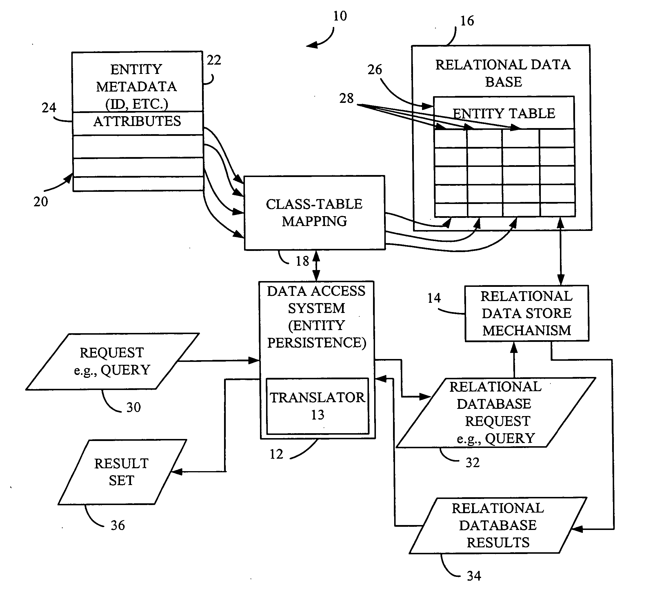
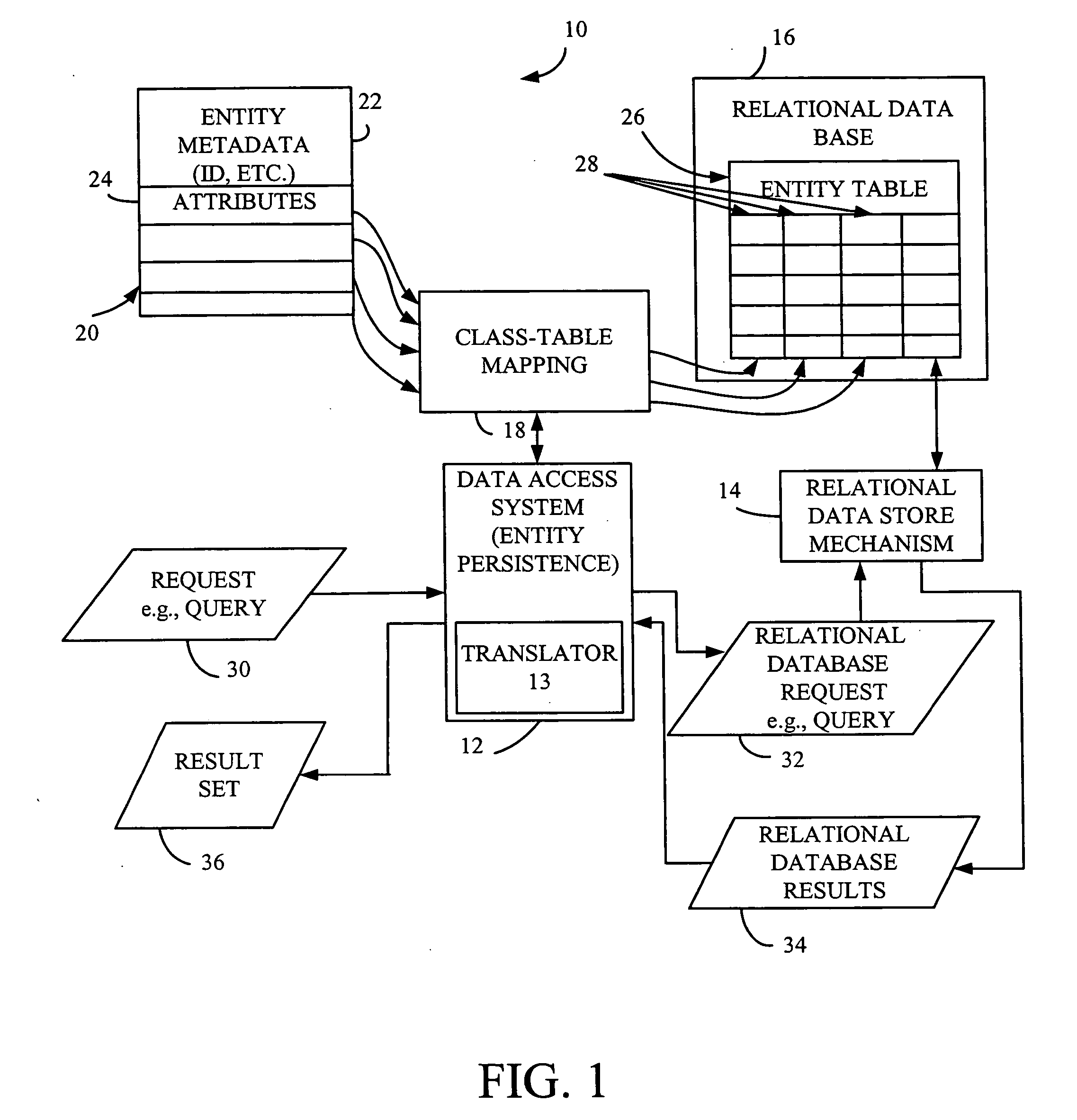
[0055]FIG. 1 is a block diagram illustrating one embodiment of a data storage and accessing system 10 in accordance with the present invention. System 10 includes data access system (or entity persistence system) 12, relational data store mechanism 14, relational database 16, and class-table mapping 18. System 10 is illustratively an object-relational (O-R) data storage system in which stored data can be referred to in terms of entities (or objects) and the...


PUM


Abstract

A dynamic filtering module receives a request to perform an operation on data in the database and a input. The dynamic filtering module provides as an output a modified request to a data access system. The modified request can include one or more restrictions added to the original request pertaining to which data will be accessed as a function of the input.

Description

CROSS REFERENCE TO RELATED APPLICATION [0001] The present application is a continuation of and claims priority of U.S. patent application Ser. No. 10 / 199,489, filed Jul. 20, 2002, the content of which is hereby incorporated by reference in its entirety.BACKGROUND OF THE INVENTION [0002] The present invention relates to database systems. In conventional relational databases, all data are stored in named tables. The tables are described by their features. In other words, the rows of each table contain items of identical type, and the definitions of the columns of the table (i.e., the column names and the data types stored in the column) describe the attributes of each of the instances of the object. By identifying its name, its column names and the data types of the column contents, a table is completely described. Queries to a relational data base are formulated in a query language. One such language is SQL (Structure Query Language) which is widely used in commercial relational data...

Claims


Application Information

Patent Timeline
IPC IPC(8): G06F17/30G06F7/00
CPCY10S707/99931Y10S707/99943Y10S707/99939Y10S707/99935Y10S707/99945Y10S707/99948G06F17/30867G06F17/30289G06F16/21G06F16/9535G06F16/24565
Inventor SMITH, MICHAEL DAVIDANONSEN, STEVEN P.
Owner MICROSOFT TECH LICENSING LLC
Why Eureka
Try Eureka