
System and method for reconstructing lost data in a storage system

a storage system and formula technology, applied in the field of system and method for determining reconstruction formulas for reconstruction of lost data in a storage system, can solve the problems of partial lost data needing to be recovered, requires either additional special purpose hardware or complicated and expensive software, and the published literature generally does not provide algorithms for recovering partial disk data. , to achieve the effect of lowest reconstruction cos

Inactive Publication Date: 2006-06-08
IBM CORP
View PDF16 Cites 15 Cited by
  • Summary
  • Abstract
  • Description
  • Claims
  • Application Information

AI Technical Summary

Benefits of technology

[0014] On the other hand, in an exemplary method the sequential reconstruction method can reconstruct a data element, from an input set of data elements to reconstruct, by collapsing the sequential reconstruction method to reduce cost. For example, the exemplary method can collapse the sequential reconstruction method by using implicit intermediate results to reconstruct the data element. Additionally or alternatively, the exemplary method can collapse the sequential reconstruction method by determining whether any unnecessary data elements exist in at least one strip of the plurality of lost strips that are not part of the partial strip, and combining at least a portion of steps in the sequential reconstruction method to eliminate reconstruction of the unnecessary data elements. Further, the exemplary method can collapse the sequential reconstruction method by avoiding unnecessary use of data elements that are not lost, avoiding duplicate use of data elements that are not lost, and / or avoiding multiple use of data elements that are not lost.
[0016] According to the exemplary aspects of the present invention, from an input set of data elements to reconstruct, the exemplary method can identify at least one data element which has a lowest reconstruction cost using the direct reconstruction method, reconstruct the data element using the direct reconstruction method, and remove the data element from the input set of data elements to reconstruct.
[0017] On the other hand, from the input set of data elements to reconstruct, another exemplary method can determine if at least one data element from the input set is sequentially reconstructable by no more than (i.e., equal to or less than) a predetermined number of steps of the sequential method using available data and parity elements, can reconstruct the data element using the sequential reconstruction method, and can remove the data element from the input set of data elements to reconstruct.
[0018] If at least one data element from the input set is not sequentially reconstructed by no more than (i.e., equal to or less than) a predetermined number of steps using available data and parity elements, an exemplary aspect of the invention can identify at least one other data element, from the input set of data elements to reconstruct, which has a lowest reconstruction cost using the direct reconstruction method. Such lowest cost reconstruction may be determined from the values determined in the first application of the direct reconstruction method (e.g., from values computed in earlier steps of the present method) or the lowest cost reconstruction may be determined either by a reapplication of the direct reconstruction method after recovery of the last data element or by feeding the recovered data element information back into the direct method reverse incremental algorithm. This exemplary method can reconstruct the other data element (or data elements) using the direct reconstruction method, and remove the other data element (or data elements) from the input set of data elements to be reconstructed.
[0020] In another exemplary system, the means for reconstructing reconstructs a data element, from an input set of data elements to reconstruct, by collapsing the sequential reconstruction method to reduce cost. The exemplary means for reconstructing can collapse the sequential reconstruction method by using implicit intermediate results to reconstruct the data element, by determining whether any unnecessary data elements exist in at least one strip of the plurality of lost strips that are not part of the partial strip, and combining at least a portion of steps in the sequential reconstruction method to eliminate reconstruction of the unnecessary data elements, by avoiding unnecessary use of data elements that are not lost, by avoiding duplicate use of data elements that are not lost, and / or by avoiding multiple use of data elements that are not lost.
[0026] More particularly, the exemplary aspects of the system and method according to the present invention are capable of being applied in many (e.g., all) situations, and can outperform the related art methods in many (e.g., all) instances (e.g., as described below with reference to FIG. 9). Further, the exemplary aspects of the present invention do not reconstruct any data elements that are not needed, thereby reducing the cost of reconstructing the data elements. As mentioned above, such costs can affect the performance of a storage system, since the costs may consume limited resources such as CPU, memory bandwidth, disk IO capacity, or XOR engine resources.

Problems solved by technology

However, this is very complicated and typically requires either additional special purpose hardware or complicated and expensive software.
The published literature generally does not provide algorithms for recovering partial disk data.
However, there are scenarios where partial lost data needs to be recovered, but not all the lost data is required.
Because the typical reconstruction algorithms are sequential in nature and are designed to recover all the lost data, they may not be the most cost effective approaches to reconstruction of partial strips.
For example, when the required partial disk data elements appear in the middle or at the end of the recurrence, these methods require reconstructing all the elements in the recurrence prior to the desired lost elements, and therefore consume extra resources reconstructing unnecessary data elements.
However, such an application does not necessarily take into account that after some data elements are reconstructed, these newly reconstructed data elements may offset the direct cost of reconstructing other data elements nor does it take into account any “geometry” or patterns in the data / parity relations that are found in the design of particular erasure codes.

Method used


Image

  • System and method for reconstructing lost data in a storage system
  • System and method for reconstructing lost data in a storage system
  • System and method for reconstructing lost data in a storage system

Examples


Embodiment Construction

[0037] Referring now to the drawings, and more particularly to FIGS. 1-9, there are shown exemplary embodiments of the method and systems according to the present invention.

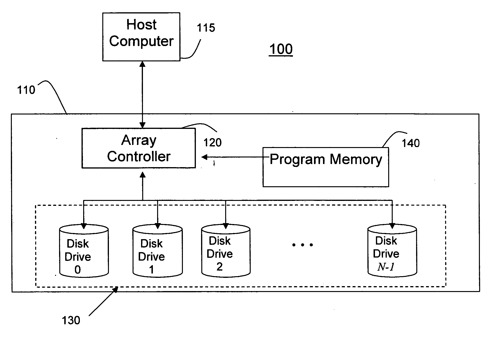
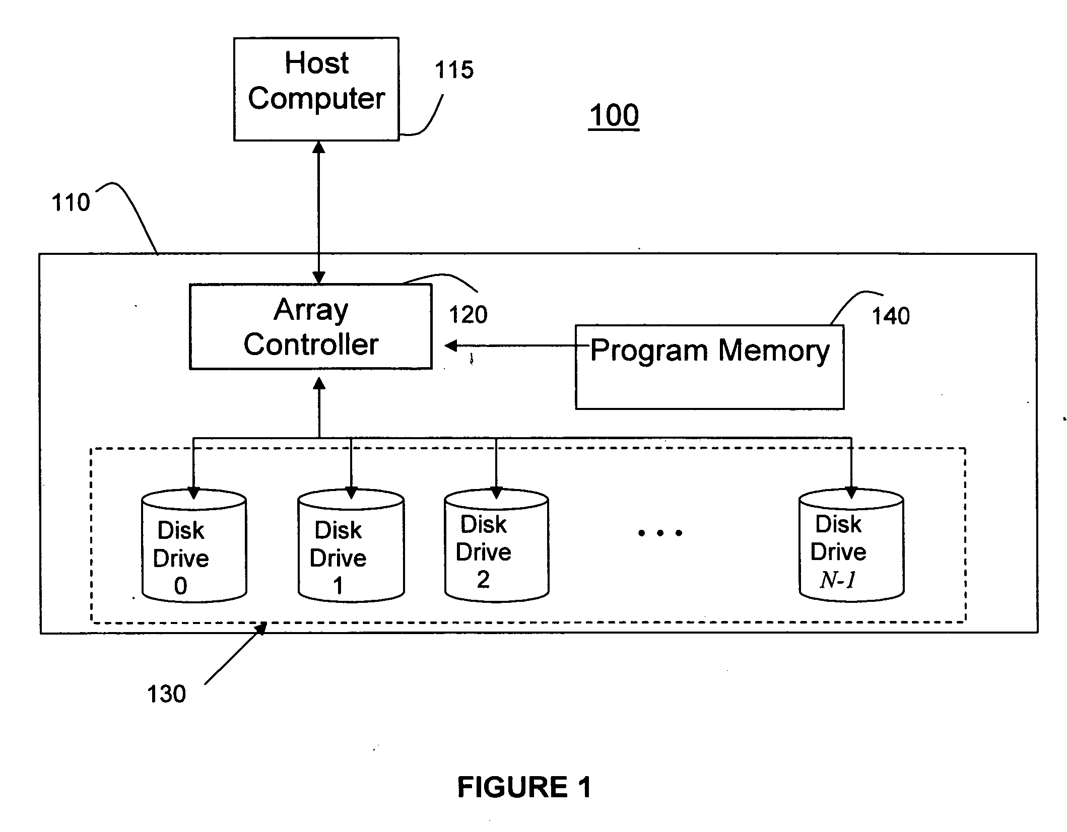
[0038] With reference to the Figures, FIG. 1 illustrates an exemplary environment in which a system and associated method (collectively referred to as “the present system”110) can be implemented. A host computer 115 is connected to an array controller 120 of system 110. The host computer 115 stores data on the array controller 120. The array controller uses a program or logic extracted from the program memory 140 to determine redundancy values (hereinafter referred to as parity values) for the data according to the erasure code of the system 110, and stores the data and parity values in the disk drives 130. If sector losses are detected by the array controller 120 when accessing one or more of the disk drives 130, then the array controller calls on additional program instructions from the program memory 140 that...


PUM


Abstract

A system (and method) for determining reconstruction formulas for partial strip reconstruction in a storage system in which a plurality of lost strips have been detected, includes using a combination of a direct reconstruction method and a sequential reconstruction method.

Description

CROSS-REFERENCE TO RELATED APPLICATION [0001] The present application is related to U.S. patent application Ser. No. 10 / 978,389, filed on Nov. 2, 2004, to Hafner et al., entitled “SYSTEM AND METHOD FOR RECOVERY OF DATA FOR A LOST SECTOR IN A STORAGE SYSTEM” having IBM Docket No. YOR920040318US1, assigned to the present assignee and which is incorporated herein by reference, in its entirety.BACKGROUND OF THE INVENTION [0002] 1. Field of the Invention [0003] The present invention generally relates to a system and method for determining reconstruction formulas for reconstruction of lost data in a storage system, and more particularly, to a system and method for determining reconstruction formulas for partial strip reconstruction including a combination of a direct reconstruction method and a sequential reconstruction method. [0004] 2. Description of the Related Art [0005] Generally, erasure codes (e.g., RAID schemes) are fundamental tools for providing data reliability in storage syste...

Claims


Application Information

Patent Timeline
IPC IPC(8): G11C29/00
CPCG06F11/1088G06F2211/1057
Inventor DEENADHAYALAN, VEERA W.HAFNER, JAMES LEESURUGUCCHI, KRISHNAKUMAR RAO
Owner IBM CORP
Learn More