
Inserting local signals during channel changes

a local signal and channel technology, applied in the direction of electrical cable transmission adaptation, digital non-picture data transmission, analog secracy/subscription systems, etc., can solve the problems of significant delay in displaying the desired program to the viewer, change delay is somewhat waste of resources, and is particularly noticeable and annoying. , to achieve the effect of improving compression efficiency and slow channel surfing

Inactive Publication Date: 2006-06-08
PRIME RES ALLIANCE E LLC
View PDF35 Cites 46 Cited by
  • Summary
  • Abstract
  • Description
  • Claims
  • Application Information

AI Technical Summary

Benefits of technology

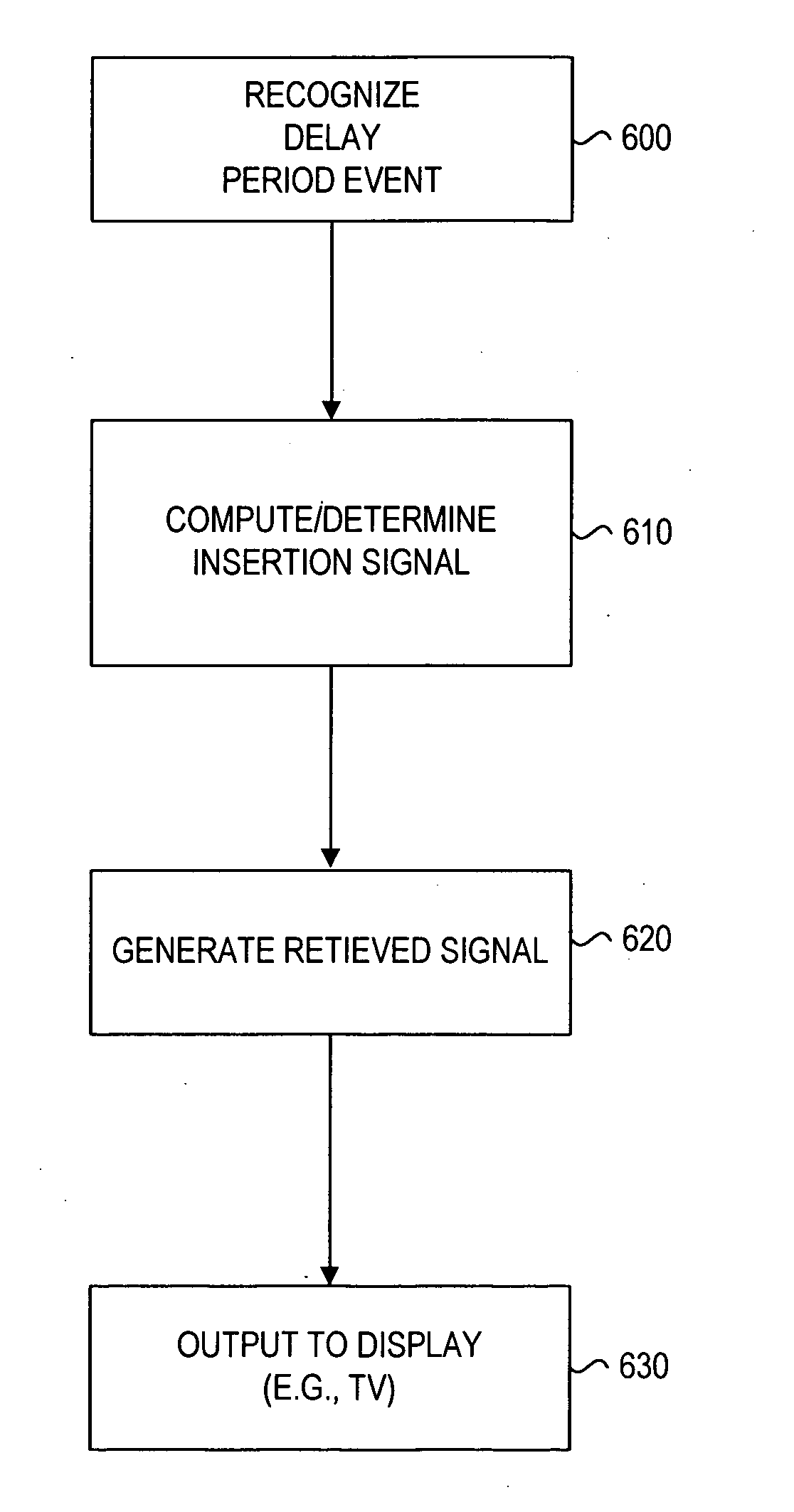
[0014] The present invention discloses an apparatus and a method for inserting and displaying one or more signals during processing and display delays encountered in digital STB-receivers, including those delays encountered during channel changes. Moreover, the invention provides a means for increasing the channel change delay period, while maintaining subscriber satisfaction, and thereby freeing up bandwidth for other services.
[0021] According to one objective of the invention, by entertaining the viewer during the current channel change delay, the present invention allows for longer refresh times (i.e., delays), which may allow for a significant improvement in compression efficiency. Thus providing a “seamless” channel change experience to the viewer and an opportunity to present advertisements, while reallocating bandwidth for additional services. This would also make channel surfing slower, which may please advertisers without causing annoyance to the viewers. Slower channel surfing may encourage viewers to rely on an Interactive Program Guide (IPG) more often, thus presenting additional advertising impressions for content included on the IPG screens.

Problems solved by technology

Because no regulation of the delivery rate is possible, a stream of data must be processed in real-time as it arrives.
All of this processing requires time that may ultimately introduce significant delays in the displaying the desired program to the viewer.
This can be particularly noticeable and annoying during channel changes.
These channel change delays are somewhat wasteful of resources, in that nothing is displayed during the delay, and can be quite annoying to the viewer.
Currently, channel changes to digital channels are slow and annoying to the viewer.
A great deal of effort and transmission bandwidth is expended to minimize this problem.
Meeting this requirement consumes approximately 20% of total transmission and storage capacity.

Method used


Image

  • Inserting local signals during channel changes
  • Inserting local signals during channel changes
  • Inserting local signals during channel changes

Examples


Embodiment Construction

[0031] In describing a preferred embodiment of the invention illustrated in the drawings, specific terminology will be used for the sake of clarity. However, the invention is not intended to be limited to the specific terms so selected, and it is to be understood that each specific term includes all technical equivalents which operate in a similar manner to accomplish a similar purpose.

[0032] With reference to the drawings, in general, and FIGS. 3 through 6 in particular, the apparatus of the present invention is disclosed.

[0033]FIGS. 4 and 5 illustrate an overview of some of the important processes entailed in the extraction, decoding and presentation of a particular program, at the set-top receiver, of an MPEG-2 transport stream according to one embodiment of the present invention. As illustrated in FIG. 4, the transport stream 436 is “demuxed” by a transport demultiplexer 442 (which includes a clock extraction mechanism), unpacketized by a depacketizer 450, and sent for audio a...


PUM


Abstract

An apparatus and a method for inserting and displaying one or more signals during processing and display delays encountered in digital STB-receivers, including those delays encountered during channel changes. Moreover, a means for increasing the channel change delay period, while maintaining subscriber satisfaction, and thereby freeing up bandwidth for other services, is provided. These signals can be advertisements, entertainment, or other messages. When a channel change request occurs on a digital set-top receiver, a local watchdog module detects the channel change event and causes to be generated a signal that is immediately displayed on the TV, while the MPEG-2 subsystem of the receiver acquires, stores, decodes and presents the new program to the television. Providing advertisements or entertainment during the delay period allows for increase in the delay period thus allowing for higher compression and increased availability of bandwidth.

Description

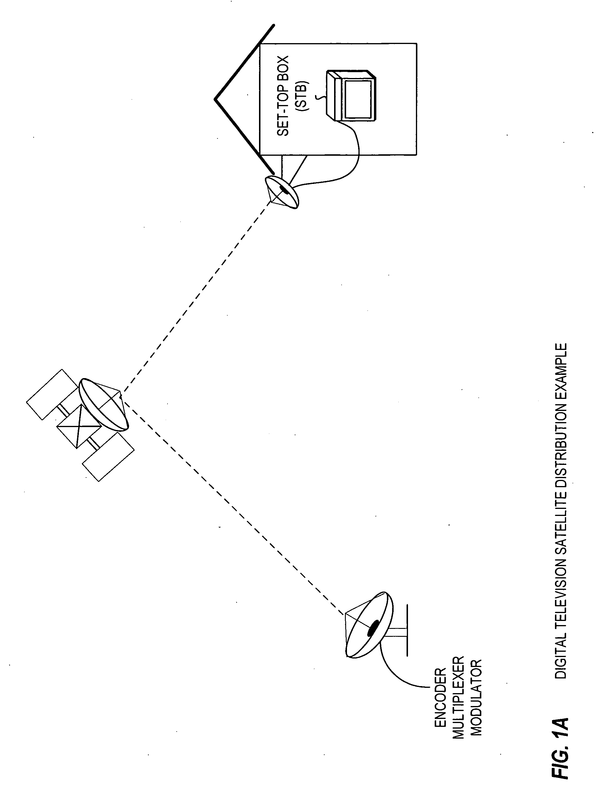
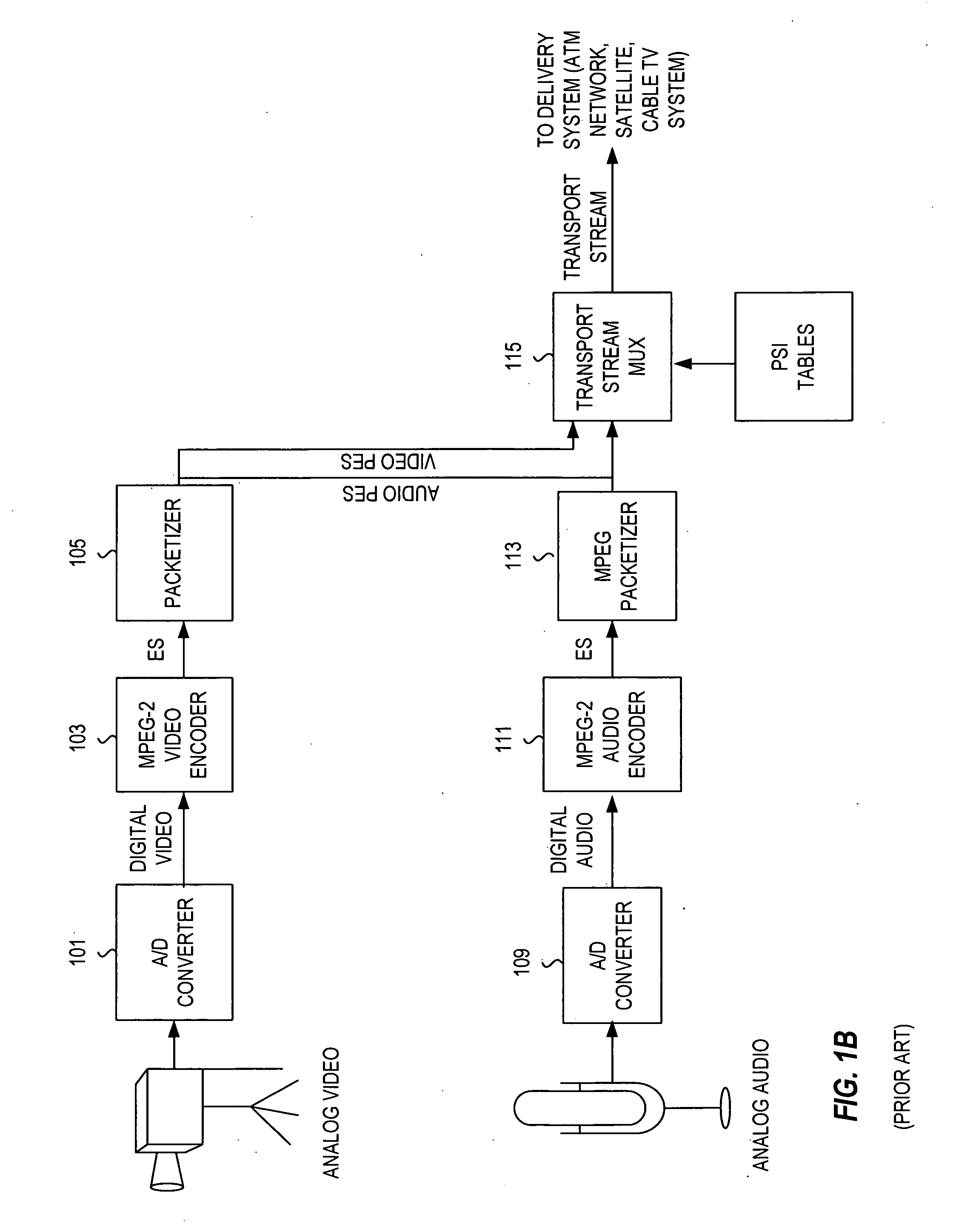
CROSS REFERENCE TO RELATED APPLICATION [0001] This application is a continuation of co-pending patent application Ser. No. 09 / 751,349, filed Dec. 28, 2000, and entitled “Inserting Local Signals during MPEG Channel Changes,” the entire disclosure of which is herein incorporated by reference.BACKGROUND OF THE INVENTION [0002] Delivering television programs in a digital format provides many advantages. Quality is improved because transmission noise does not accumulate in the picture or sound signals, providing cleaner video and audio. The ability to compress the digital information allows for the delivery of multiple programs over the same bandwidth traditionally used for only one analog program, thus providing viewers and operators with more programming choices. Also, additional services can be added for data broadcasting and interactivity. The MPEG-2 standard was developed, inter alia, to address the delivery of digital video, and to facilitate the development of interoperable compon...

Claims


Application Information

Patent Timeline
IPC IPC(8): H04N7/10H04N7/16H04N7/025H04N5/44H04N5/50H04N21/433H04N21/434H04N21/438H04N21/44H04N21/458H04N21/478H04N21/81
CPCH04N5/4401H04N5/50H04N21/4331H04N21/434H04N21/4383H04N21/4384H04N21/44016H04N21/458H04N21/478H04N21/812H04N21/426
Inventor HAMILTON, JEFFREY S.FLICKINGER, GREGORY C.
Owner PRIME RES ALLIANCE E LLC
Learn More