Window element for insertion in a window aperture in an outer skin of a transport

a technology for window apertures and outer skins, applied in transportation and packaging, heating types, lighting and heating apparatus, etc., can solve the problems of aerodynamic disadvantage, increased drag, and known bulges or deformations of windows, and achieve the effect of reducing the deformation of the cover pane and ensuring the sealability with respect to the surrounding atmospher

Active Publication Date: 2006-06-15
AIRBUS OPERATIONS GMBH
View PDF17 Cites 33 Cited by
  • Summary
  • Abstract
  • Description
  • Claims
  • Application Information

AI Technical Summary

Benefits of technology

[0013] A window element has a cover pane which is substantially flush with the outer skin in order to achieve a fluid dynamically favorable, largely flat shape of the outer skin. Thus, a highly aerodynamic outer skin is obtained, independently of any deformation of the outer pane of the window element due to the difference between the cabin internal pressure at cruising altitudes. In addition, the window element according to one embodiment of the invention, can be mounted simply, easily and rapidly into a window aperture in an aircraft fuselage airframe or fuselage cell. Further, some of the components required to form the window element according to one embodiment of the invention can be produced easily, due to manufacturing technology with the required high dimensional stability, for example, the use of fibre-reinforced plastics in injection moulding.
[0014] According to one embodiment, the window element comprises a window frame with an outer face. The outer face is joinable, at least in certain areas, to an inner face of the outer skin in an edge area of the window aperture. Such a feature may ensure easy mounting of the window frame in a window aperture of the aircraft outer skin.
[0015] According to one embodiment of the window frame, a supporting frame inside the window aperture rests on the outer face at least in certain areas. This embodiment may ensure that further add-on pieces of the window element can easily be mounted from the inside of the aircraft.

Problems solved by technology

A window frame with a T-shaped cross-sectional geometry is known; however, such a window is known to bulge or deform as the pressure difference changes during ascent to cruising altitude.
This deformation increases drag and is aerodynamically disadvantageous.
The window elements comprising window frames, that are currently used, have very complex constructions as a result of the numerous requirements described hereinbefore.
As a consequence of the required expensive construction of the window frames, the plurality of additional connecting elements and the supporting frame, the weight of the known window elements is very high.
In addition, assembly of the described window elements is expensive.
In addition, aerodynamic adverse effects are frequently produced by using the currently used window elements in fuselage airframes of aircraft.
Thus, the outer panes of the window elements used are not always completely flush with the outer skin in all sections of the aircraft fuselage.
These described aerodynamic effects results in perturbations of the flow around the fuselage airframe which can considerably impair the aerodynamic quality of the outer skin of the fuselage airframe of an aircraft, especially if a large number of window elements is used in the fuselage airframe.
As a result of previously indicated disadvantages of the of window elements, often used currently these are only suitable to a limited extent for use in aircraft having large dimensions and a large number of window elements resulting therefrom.

Method used


Image

  • Window element for insertion in a window aperture in an outer skin of a transport
  • Window element for insertion in a window aperture in an outer skin of a transport
  • Window element for insertion in a window aperture in an outer skin of a transport

Examples


Embodiment Construction

[0026] As a result of previously indicated disadvantages of the of window elements, often used currently these are only suitable to a limited extent for use in aircraft having large dimensions and a large number of window elements resulting therefrom.

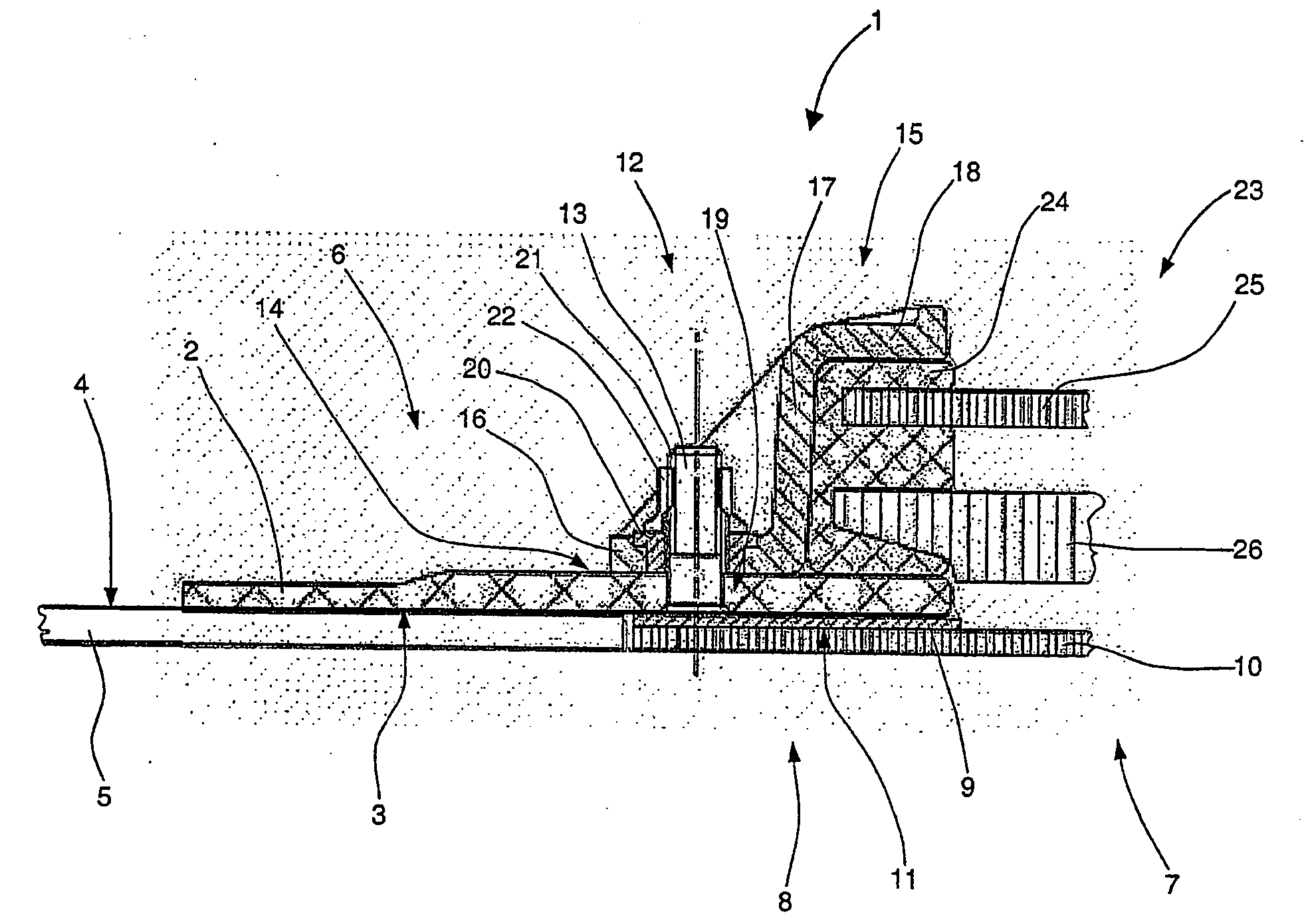
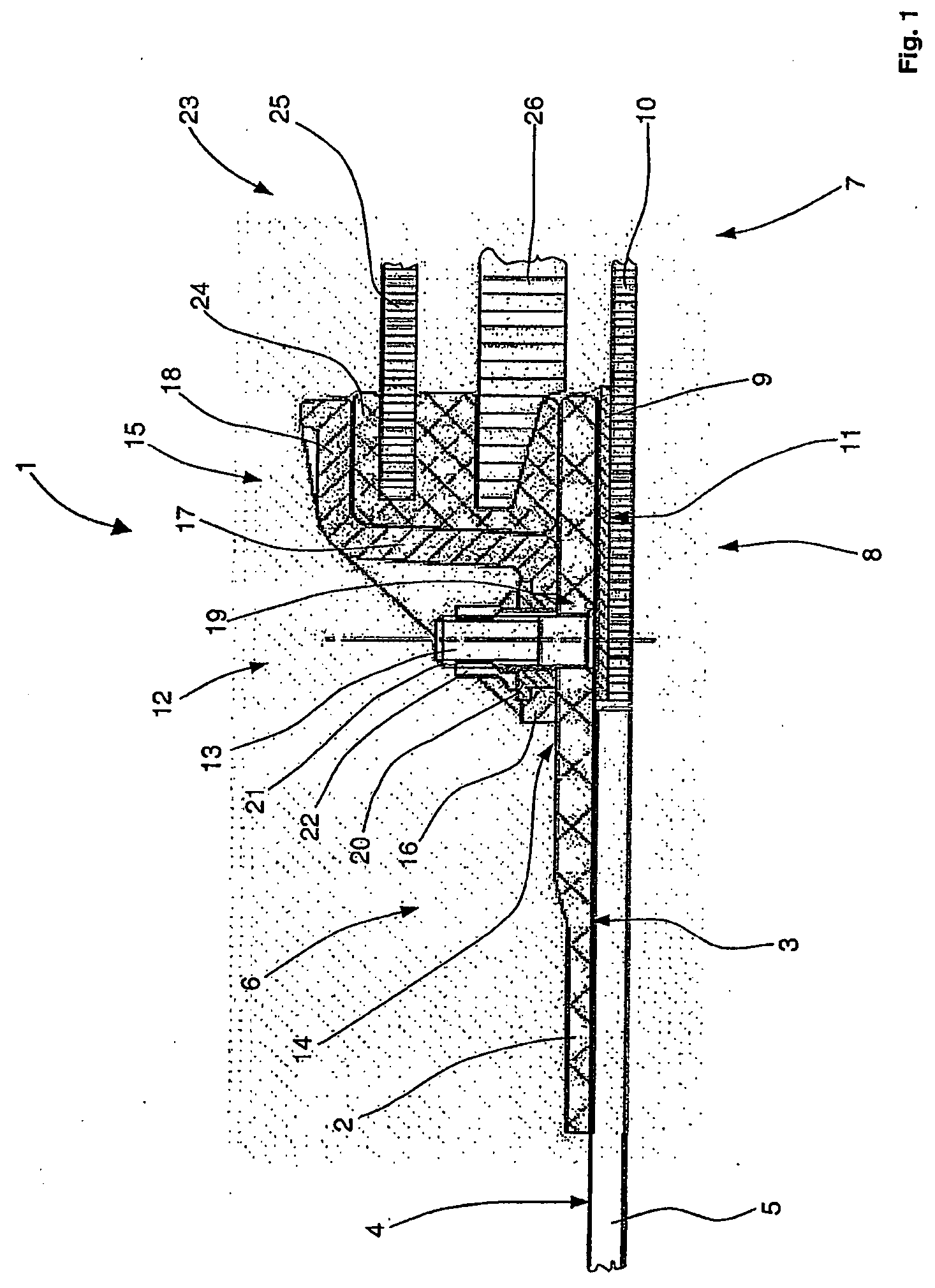
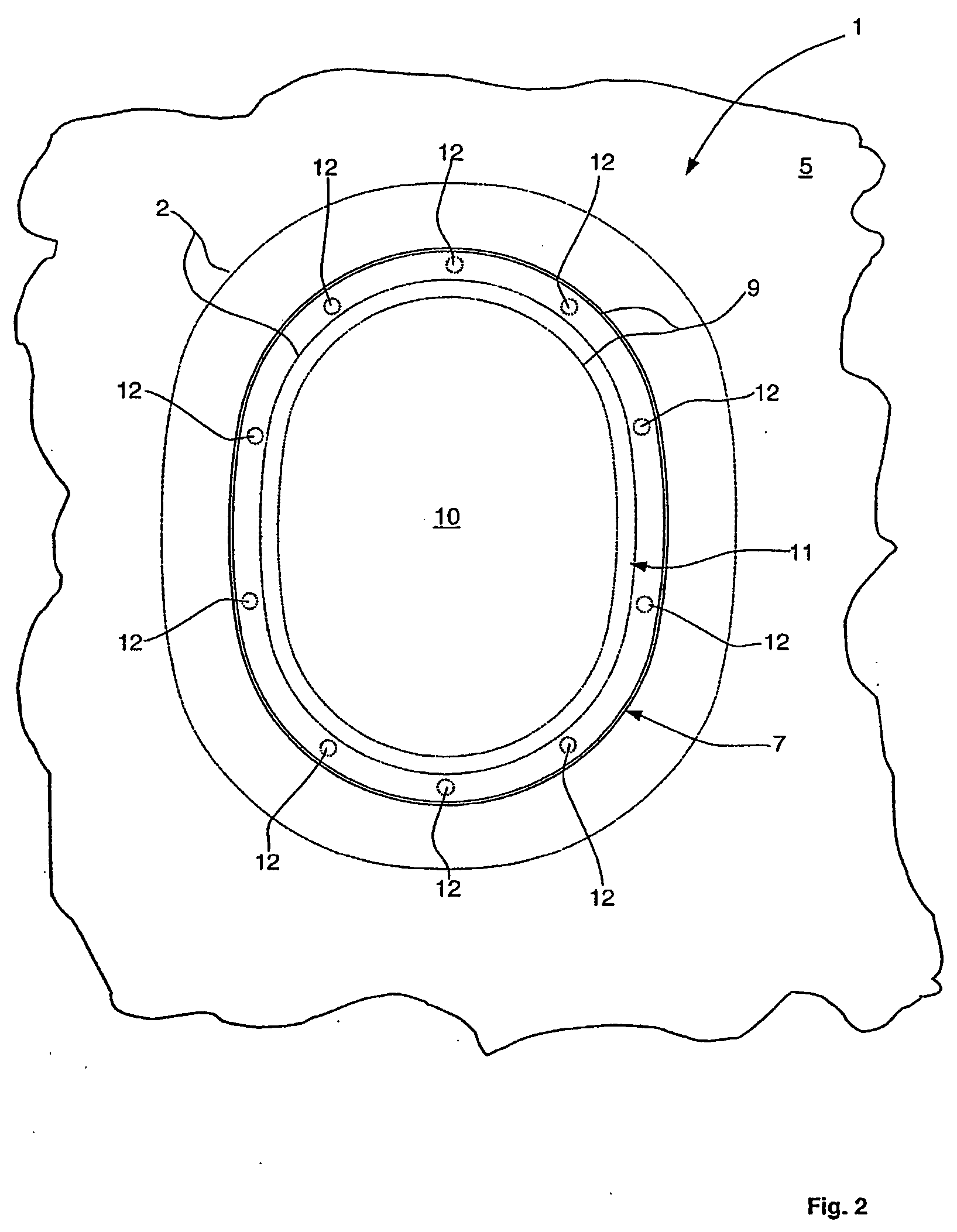
[0027]FIG. 1 illustrates a cross-section of a portion of a window element according to one embodiment of the invention. The window element 1 comprises a window frame 2 with a window-frame outer face 3. The window frame 2 has a substantially rectangular cross-sectional geometry. The window frame 2 according to the one embodiment of the invention based on known window elements for aircraft, substantially has an oval, circular, elliptical or angular or polygonal circumferential contour with optionally rounded edges, as illustrated in FIG. 2, for example.

[0028] In reference to FIG. 1, the window frame 2 rests with the window-frame outer face 3 partly on an outer-skin inner face 4 of an outer skin 5 in the edge area 6 of a window aperture ...


PUM


Abstract

A window element has a cover pane which is substantially flush with an outer skin of an aircraft or other transport, achieving a fluid-dynamically favourable, substantially unbulged exterior surface. As a result of the presence of an additional back-ventilated cover pane 10 arranged in front of the actual outer pane of the window element, a fluid-dynamically favourable integration of the window element into the outer skin of an aircraft fuselage airframe is achieved. Any deformation, such as any buckling or bulging of the outer pane of the window element, as a result of a difference in pressure between the interior of the aircraft fuselage airframe and the exterior space at cruising altitudes, has no fluid-dynamically disadvantageous effect. The outer pane is covered by the cover pane which remains substantially undeformed with respect to the outer skin of the aircraft fuselage airframe, for example. Any deformation of the cover pane is largely eliminated by this back-ventilation.

Description

RELATED APPLICATION [0001] This application claims the benefit of the filing date of German Patent Application No. 10 2004 050 399.0 filed Oct. 15, 2004, the disclosure of which is hereby incorporated herein by reference. FIELD OF THE INVENTION [0002] The field is structural engineering in the transportation industry, specifically aircraft windows. TECHNOLOGICAL BACKGROUND [0003] Numerous variations of window elements for insertion in fuselage airframes of aircraft are known from reference in the field. Some of these window elements have a forged window frame made of aluminium which forms the actual supporting structure of the window element. A window frame with a T-shaped cross-sectional geometry is known; however, such a window is known to bulge or deform as the pressure difference changes during ascent to cruising altitude. This deformation increases drag and is aerodynamically disadvantageous. [0004] A conventional window frame has a circumferential fixing flange with a circumfe...

Claims


Application Information

Patent Timeline
Patent Type & Authority Applications(United States)
IPC IPC(8): E06B1/04
CPCB64C1/1492
Inventor PASPIRGILIS, BERND
Owner AIRBUS OPERATIONS GMBH
Why Eureka
Try Eureka