Catalytic converter degradation

Inactive Publication Date: 2006-06-15
NISSAN MOTOR CO LTD
View PDF8 Cites 9 Cited by
  • Summary
  • Abstract
  • Description
  • Claims
  • Application Information

AI Technical Summary

Benefits of technology

[0008] The present invention was conceived in view of this shortfall. One object of the present invention is to provide a catalytic converter degradation determining system that can determine if a catalytic converter is degraded even under lean engine operating conditions.

Problems solved by technology

However, dual O2 sensor systems are not able to determine the degradation of the catalytic converter in diesel engines and other engines that are normally run lean (i.e., with a lean air-fuel mixture).

Method used


Image

  • Catalytic converter degradation
  • Catalytic converter degradation
  • Catalytic converter degradation

Examples


Embodiment Construction

[0017] Selected embodiments of the present invention will now be explained with reference to the drawings. It will be apparent to those skilled in the art from this disclosure that the following descriptions of the embodiments of the present invention are provided for illustration only and not for the purpose of limiting the invention as defined by the appended claims and their equivalents.

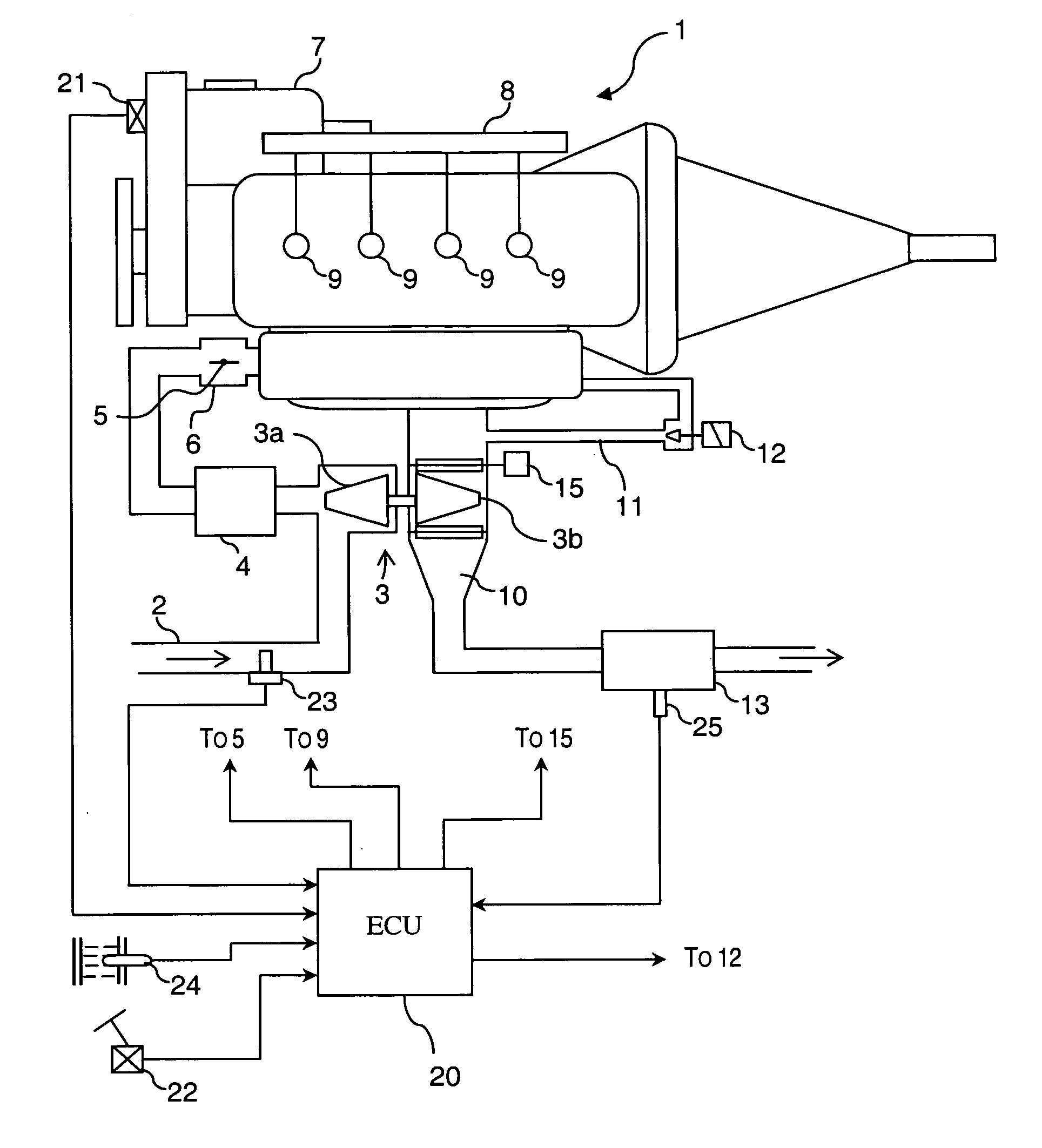
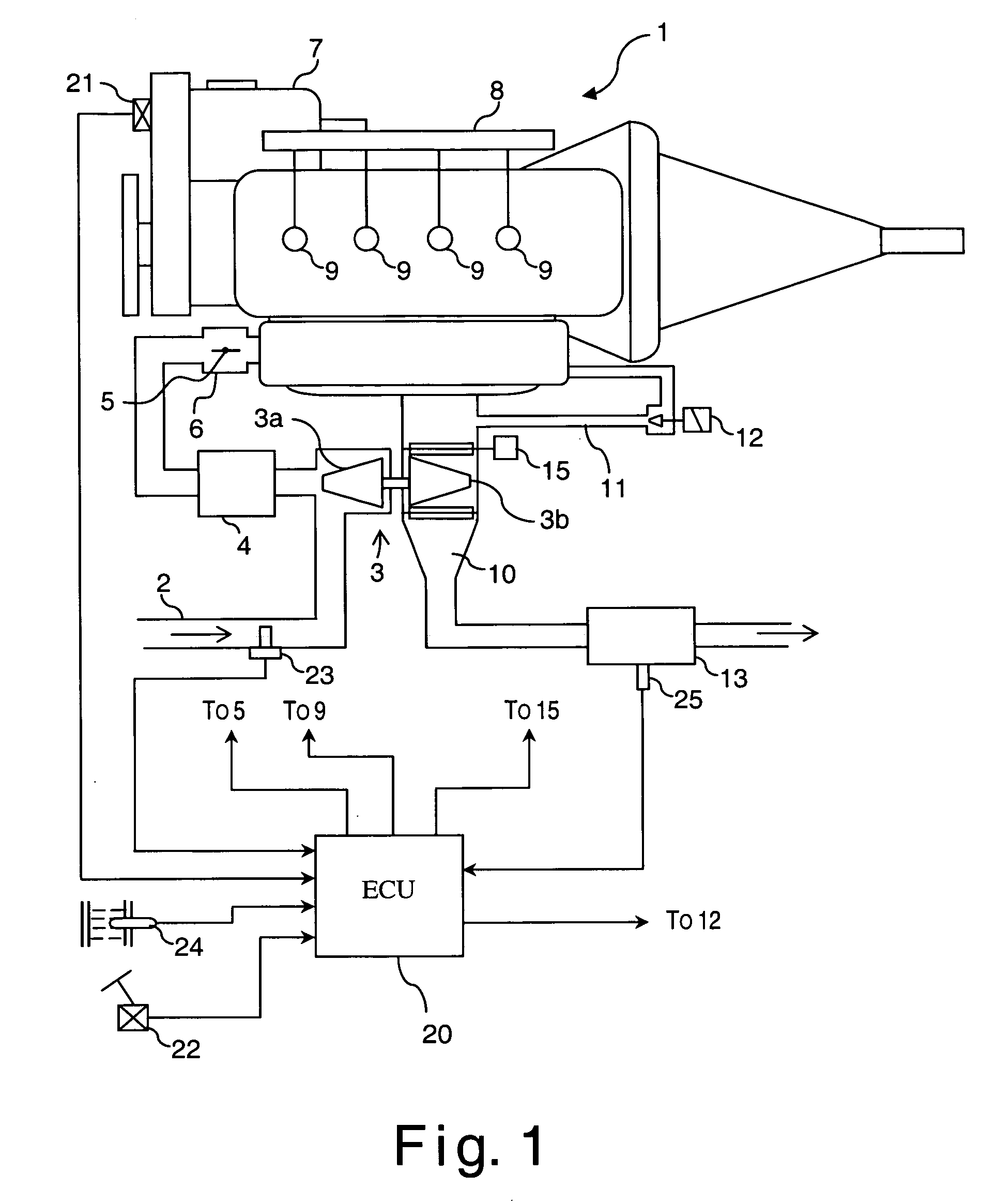
[0018] Referring initially to FIG. 1, a schematic diagram of a direct injection diesel engine 1 is illustrated in accordance with a first embodiment of the present invention. The diesel engine 1 is preferable used in an automobile. The diesel engine 1 is well known in the art. Since diesel engines are well known in the art, the precise structure of the diesel engine 1 will not be discussed or illustrated in detail herein. An air cleaner (not shown) is installed at an inlet part of an air intake passage 2 to remove dust and particles from intake air to the diesel engine 1. A variable nozzle turboc...


PUM


Abstract

A catalytic converter degradation determining system is configured to accurately determine if a NOx trapping catalytic converter is degraded. The system is configured to detect or estimate the temperature of a NOx trapping catalytic converter and sets a pre-degradation adsorption efficiency and a post-degradation adsorption efficiency based on the catalytic converter temperature. The system then multiplies the adsorption efficiencies by an exhaust gas NOx quantity to calculate trapped NOx rates. The individual trapping NOx rates are summed over a prescribed amount of time to estimate the pre-degradation and post-degradation NOx trapping amounts. After the prescribed amount of time elapses, the system compares the pre-degradation NOx trapping amount to the post-degradation NOx trapping amount and determines if the difference between the two is smaller than a prescribed value. If the difference is smaller than the prescribed value, then the system determines that the catalytic converter is degraded.

Description

CROSS-REFERENCE TO RELATED APPLICATIONS [0001] This application claims priority under 35 U.S.C. § 119 to Japanese Patent Application No. 2004-361094. The entire disclosure of Japanese Patent Application No. 2004-361094 is hereby incorporated herein by reference. BACKGROUND OF THE INVENTION [0002] 1. Field of the Invention [0003] The present invention generally relates to a degradation determining system for an exhaust gas cleaning catalytic converter configured to be arranged in an exhaust passage of an internal combustion engine and having at least an oxidizing function (includes NOx trapping catalytic converters). [0004] 2. Background Information [0005] One example of a known catalytic converter degradation determining system is the system disclosed in Japanese Laid-Open Patent Publication No. 02-030915. That system (dual O2 sensor system) has two air-fuel ratio sensors (O2 sensors), one arranged upstream of the catalytic converter and another arranged downstream of the catalytic ...

Claims


Application Information

Patent Timeline
IPC IPC(8): F01N3/00F01N7/00B01D53/94F01N3/08F01N3/20
CPCF01N3/0814F01N3/0842F01N3/10F01N11/002F01N2250/12F01N2550/02F01N2550/03F02D2200/0811Y02T10/47Y02T10/24Y02T10/12Y02T10/40
Inventor MIURA, MANABU
Owner NISSAN MOTOR CO LTD
Why Eureka
Try Eureka