
Air injection engine

a technology of air injection and combustion engine, which is applied in the direction of machines/engines, oscillatory slide valves, output power, etc., can solve the problems of limited compression ratio of engine, and achieves significant increase or decrease in compression ratio, increase or decrease in expansion ratio, effect of increasing thermodynamic efficiency

Inactive Publication Date: 2006-06-15
D J ENG
View PDF35 Cites 34 Cited by
  • Summary
  • Abstract
  • Description
  • Claims
  • Application Information

AI Technical Summary

Benefits of technology

"The present invention provides an internal combustion engine with independent compression and expansion portions of the cycle and ratios. The engine includes a compressor, combustion cylinder, and a compressed air conduit for transferring compressed air from the compressor to the combustion cylinder. The compression and expansion ratios are controlled to optimize engine performance. The engine also uses a timed valve to control the pneumatic communication between the compressed air conduit and the combustion cylinder, allowing for a higher compression ratio and higher thermodynamic efficiency. The injection of pressurized air occurs during a small portion of the combustion cylinder cycle, and a timed valve is used to allow for timed, intermittent pneumatic communication between the compressed air conduit and the combustion chamber. This results in a more efficient engine with improved performance."

Problems solved by technology

With many prior art engines, the compression ratio of the engine is limited by the expansion ratio of the cylinders of the engine.
In other prior art engines, the compression ratio of the engine is limited to a relatively low value because auto-ignition of the fuel air mixture will occur too early in the cycle as compressed air reaches a temperature above the auto-ignition temperature of the fuel.

Method used


Image

  • Air injection engine
  • Air injection engine
  • Air injection engine

Examples


Embodiment Construction

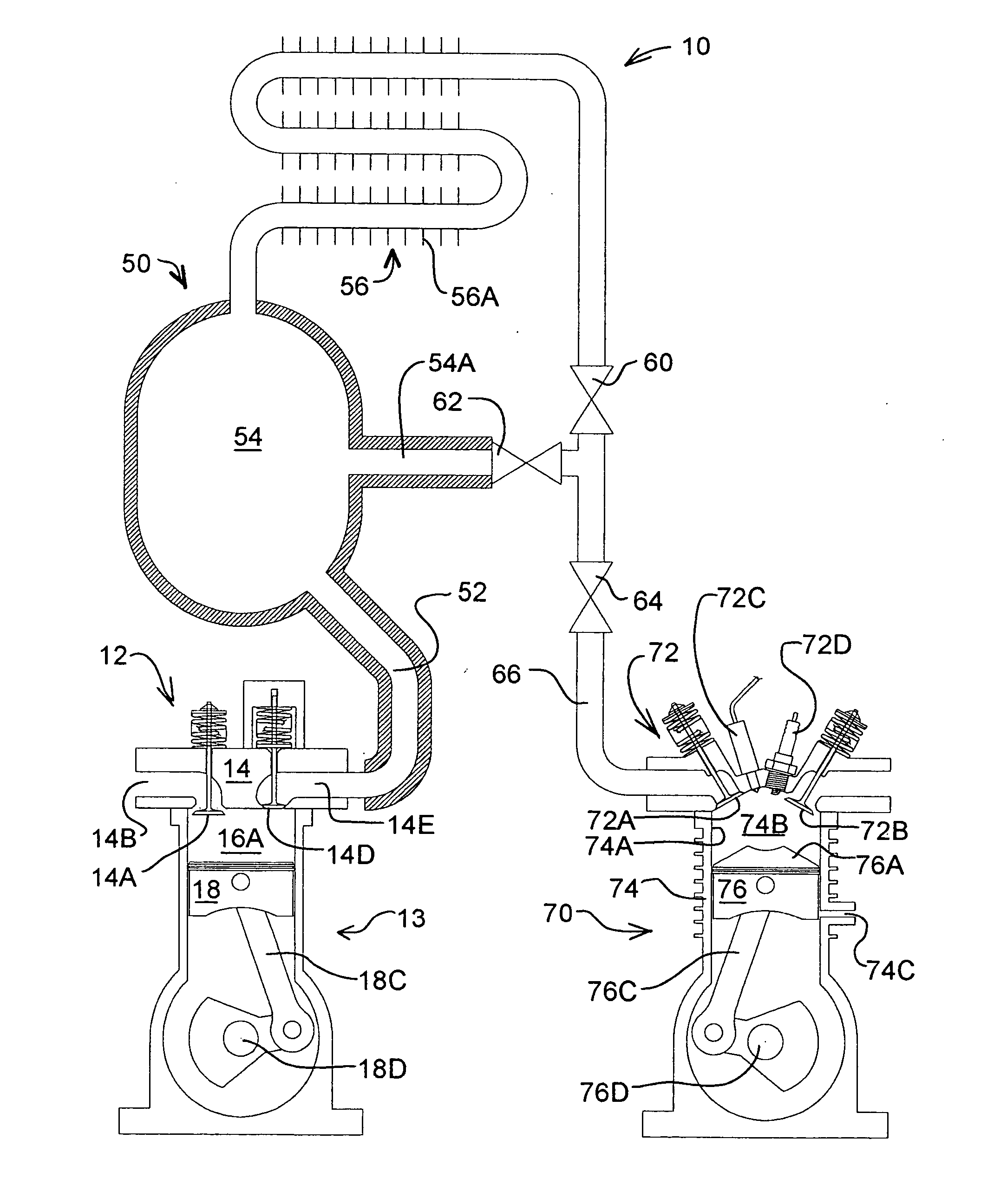
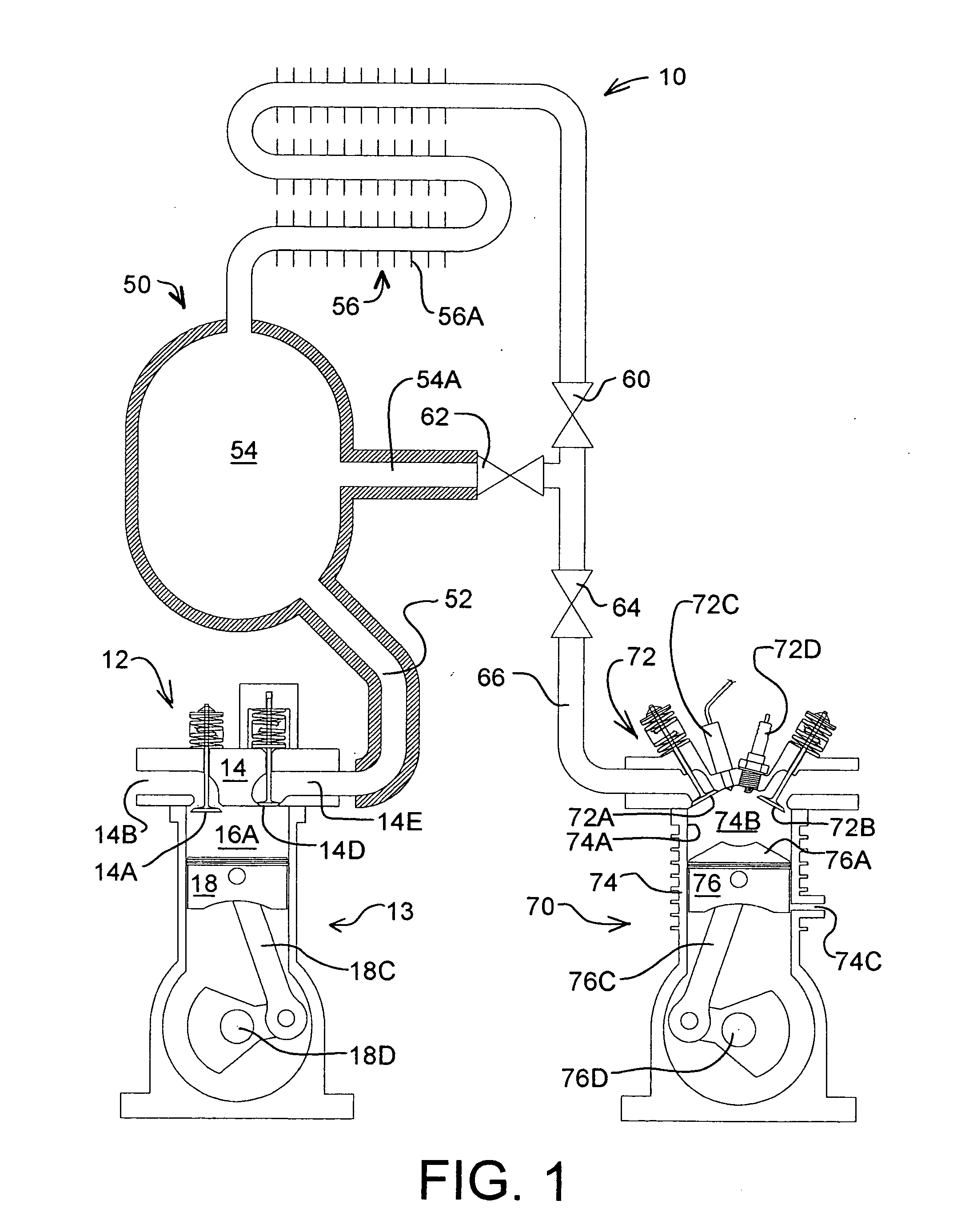
[0040] Referring to the drawings, FIG. 1 illustrates an internal combustion engine 10 in accordance with an embodiment of the invention. In FIG. 1, an-internal combustion engine 10 is shown including compressor 12, compressed air conduit 50 and combustion cylinder 70. Combustion cylinder 70 includes a cylinder 74 and a reciprocating piston 76 which is one of the mechanical arrangements for defining an internal combustion engine which features a combustion chamber that cycles between a minimum volume and a maximum volume. Combustion cylinder 70 may be one of two or more combustion cylinders coupled together on a common crankshaft 76D. Likewise compressor 12 may include a compression cylinder 13 as shown in FIG. 1. Compressor 12 provides compressed air to compressed air conduit 50. Together, compressor 12 and compressed air conduit 50 provide a source of compressed air for use by combustion cylinder 70.

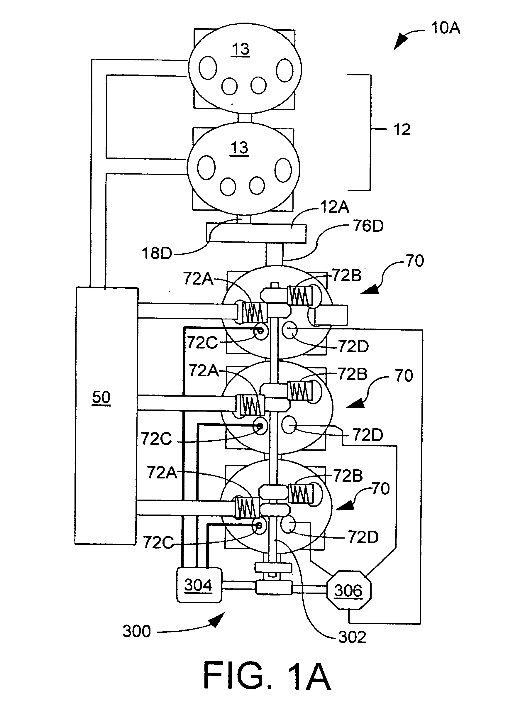
[0041]FIG. 1A schematically presents an example embodiment of the present engine 1...


PUM


Abstract

An internal combustion engine of the present invention features separate compression and expansion cycles. The engine includes a separate compressor device which pressurizes air by a ratio greater than 15 to 1, at least one two stroke combustion cylinder and a compressed air conduit for transferring compressed air from the compressor to the at least one combustion cylinder. An air injection valve injects the compressed air into the combustion cylinder during the second half portion of the return stroke of the combustion cylinder. The compressed air is mixed with fuel and combusted for expansion during a power stroke. In this engine compression occurs only to a minor degree in the combustion cylinder. Accordingly, the compression ratio of the present engine may be significantly higher or lower than the volumetric expansion ratio of the combustion cylinder thus resulting in corresponding increases in either power density or thermodynamic efficiency respectively.

Description

[0001] This application is a continuation of application Ser. No. 10 / 777,796 which was filed Feb. 12, 2004. [0002] U.S. application Ser. 10 / 777,796 claimed the benefit of U.S. Provisional Patent Application No. 60 / 446,934 filed Feb. 12, 2003.FIELD OF THE INVENTION [0003] The present invention relates to an internal combustion engine. BACKGROUND OF THE INVENTION [0004] Many types of internal combustion engines are known in the art. It is well known that increasing the compression ratio of an internal combustion engine will result in increased thermodynamic efficiency. With many prior art engines, the compression ratio of the engine is limited by the expansion ratio of the cylinders of the engine. In other prior art engines, the compression ratio of the engine is limited to a relatively low value because auto-ignition of the fuel air mixture will occur too early in the cycle as compressed air reaches a temperature above the auto-ignition temperature of the fuel. BRIEF DESCRIPTION OF T...

Claims


Application Information

Patent Timeline
Patent Type & Authority Applications(United States)
IPC IPC(8): F02B33/00F01L5/14F01L7/00F01L7/02F02BF02B1/00F02B21/00F02B23/10F02D13/02F02M23/00F17D3/00
CPCF01L5/14F01L7/02F01L2003/258F02B21/00F02B23/101F02D13/0276F02M2023/008Y02T10/125Y02T10/18Y10T137/86726Y02T10/12F02B33/00F01L7/00F17D3/00
Inventor LUTTGEHARM, CLINT ALLEN
Owner D J ENG
Learn More