Valve for liquid separation

Inactive Publication Date: 2006-06-15
AGILENT TECH INC
View PDF6 Cites 0 Cited by
  • Summary
  • Abstract
  • Description
  • Claims
  • Application Information

AI Technical Summary

Benefits of technology

[0020] It is advantageous for the opposing shut-off surfaces at the sealing surface to have a step or nose-like projection. This allows the shut-off surfaces of the sealing element to quickly reach a precise sealing position with a self-sealing effect under liquid pressure.
[0021] The opposing shut-off surface of the valve body that preferably faces the free end of the actuator narrows toward the outlet as a cone or funnel. This produces particularly good flushing behavior of the internal hydraulic volume. This does a particularly good job of diver

Problems solved by technology

A first decisive disadvantage is that a significant band widening can occur due to the valve construction, i.e., the desired separation does not occur.
This can be due to problematic channel path and design, and especially due to poor design of the valve chambers, for example from dead zones such as blind holes or cavities that are poorly flushed, or by the internal valve volume.
In addition, substantial pressure peaks can sometimes arise when the valves are switched when the channels are briefly closed and/or when there are changes in volume when switching.
These pressure peaks can lead to corresponding signal distortion in the chromatogram of the detectors used to control the valves, whereby an incorrect trigger pulse can be induced for the switching time of the valves.
This can have a catastrophic effect on the quality of the fractions to be collected.
Other disadvantages can arise in conjunction with the large construction-related forces that arise during switching and/or large forces that arise to ensure a sufficient seal when the valves are in the

Method used


Image

  • Valve for liquid separation
  • Valve for liquid separation

Examples


Example

DETAILED DESCRIPTION OF THE DRAWINGS

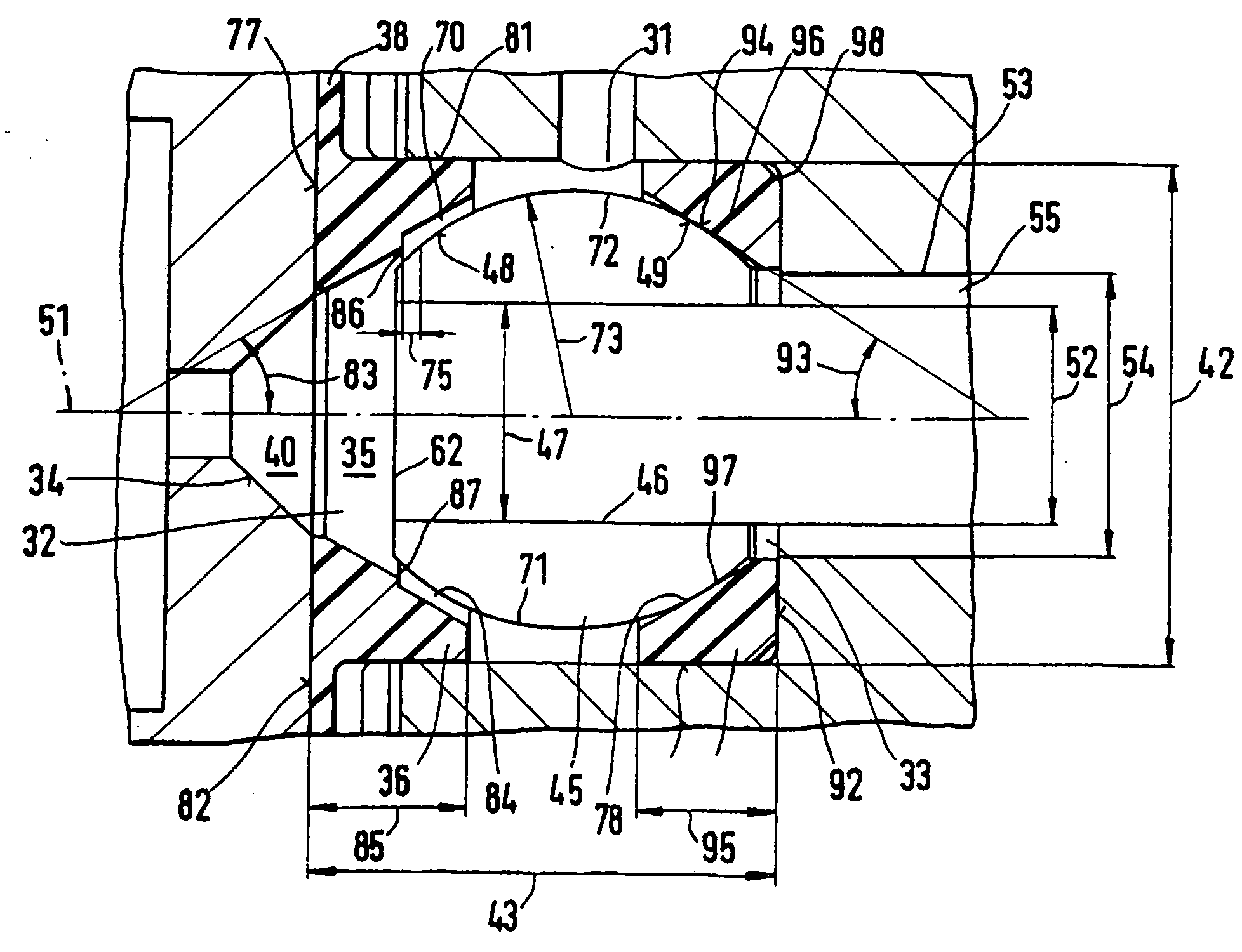
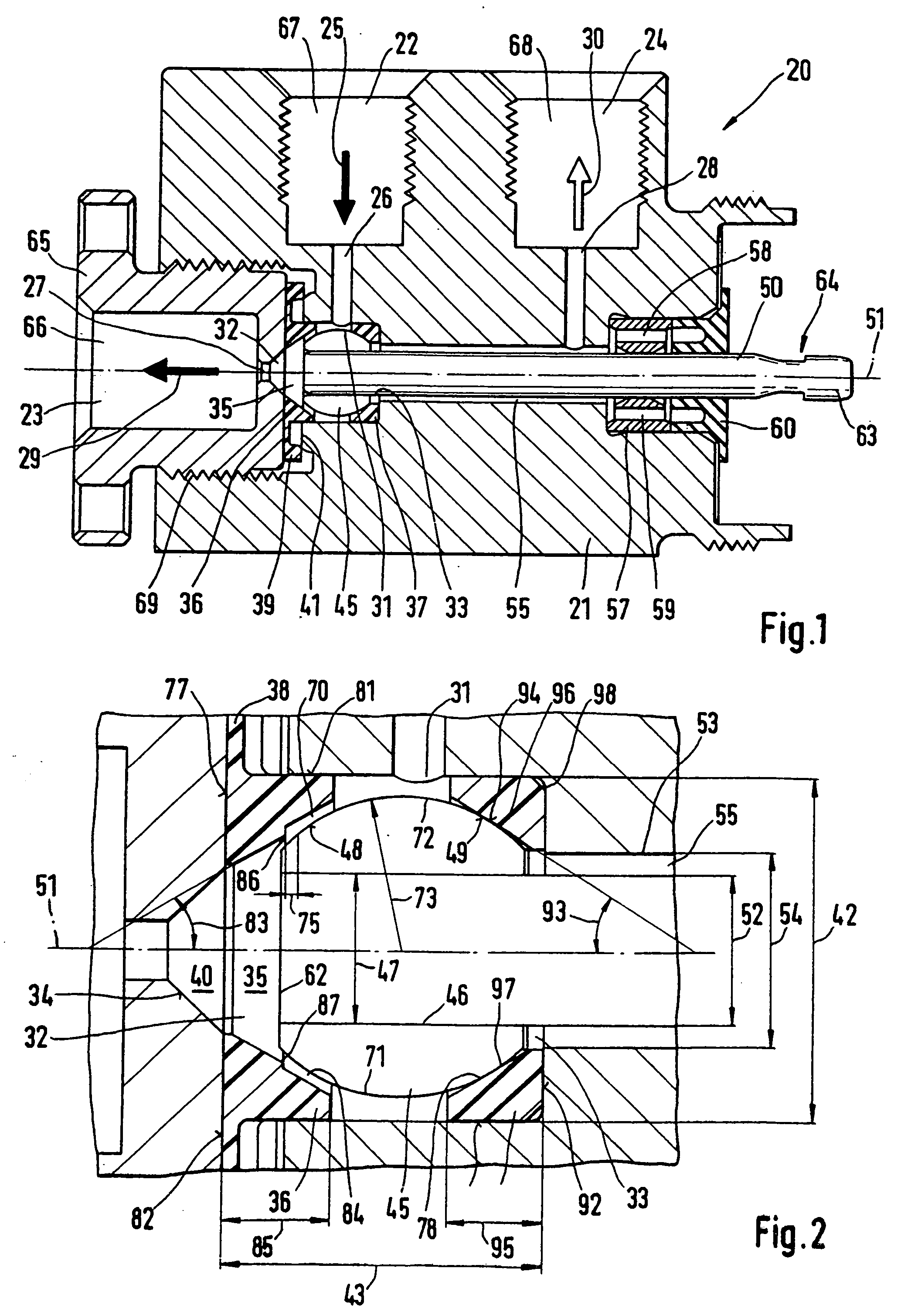
[0028] The valve 20 in FIG. 1 is designed as a three / two-way valve and has a valve body 21 with external inlet 22 and a primary external outlet 23 and secondary external outlet 24. Inlet 22 has a connecting hole 67 to connect connecting lines (not shown) and ends in the cylindrical inlet channel 26. Channel 26 ends in interior inlet 31 that is assigned to the switching chamber 35. The switching chamber 35 also has a primary interior outlet 32 and secondary interior outlet 33 that is opposite the primary interior outlet 32. The interior outlets 32, 33 are symmetrical to the actuation, i.e., longitudinal axis 51 of actuator 50 and are on opposite sides of the inlet 31 at an angle of 90° to the interior inlet.

[0029] In the switching chamber 35 is first annular valve seat 36 assigned to the primary interior outlet 32 and the second annular valve seat 37 assigned to the secondary interior outlet 33. Also in the switching chamber 35 is the switchable ...


PUM


Abstract

The invention concerns a valve (20) for liquid separation, especially for analytical or preparative liquid chromatography, with a valve body (21) that has an inlet (31) and at least two outlets (32, 33) connected to it for a flow of liquid. In the valve body (21), there is a sealing element (45) consisting of shut-off surfaces to alternately shut off the outlets (32, 33) with shut-off surfaces (48, 49) facing away from each other in the shape of a cone segment or spherical segment.

Description

RELATED APPLICATIONS [0001] The present application is a divisional application of U.S. patent application Ser. No. 09 / 672,038, filed Sep. 29, 2000, which is based on, and claims priority to, German patent application Serial No. 199 46 654.8-12, filed Sep. 29, 1999, the disclosures of which are hereby incorporated by reference in their entirety.FIELD OF INVENTION [0002] The invention concerns a valve for liquid separation, especially for analytical or preparative high performance liquid chromatography, with a valve body that has an inlet and at least two outlets that can be connected to the inlet in which a shutter element with shut-off surfaces can be used to alternately shut off the outlets directly by means of conical or spherical segment shut-off surfaces. BACKGROUND OF THE INVENTION [0003] Samples separated by means of liquid separation, e.g. analytical or preparative liquid chromatography, must be transported or collected in a suitable manner. Important criteria for the system...

Claims


Application Information

Patent Timeline
IPC IPC(8): F16K11/044F16K11/056G01N30/20
CPCF16K11/044F16K11/056G01N30/20Y10S137/901Y10T137/86895
Inventor DEHMER, BERNHARD
Owner AGILENT TECH INC
Why Eureka
Try Eureka