Elevator system

Inactive Publication Date: 2006-06-15
MITSUBISHI ELECTRIC CORP
View PDF6 Cites 23 Cited by
  • Summary
  • Abstract
  • Description
  • Claims
  • Application Information

AI Technical Summary

Benefits of technology

[0004] The present invention has been made to solve the above problem, and therefore an object of the present invention is

Problems solved by technology

Therefore, when a runaway car is due to an abnormal control panel, information from the control panel can also be abnormal, and thus

Method used


Image

  • Elevator system
  • Elevator system
  • Elevator system

Examples


embodiment 1

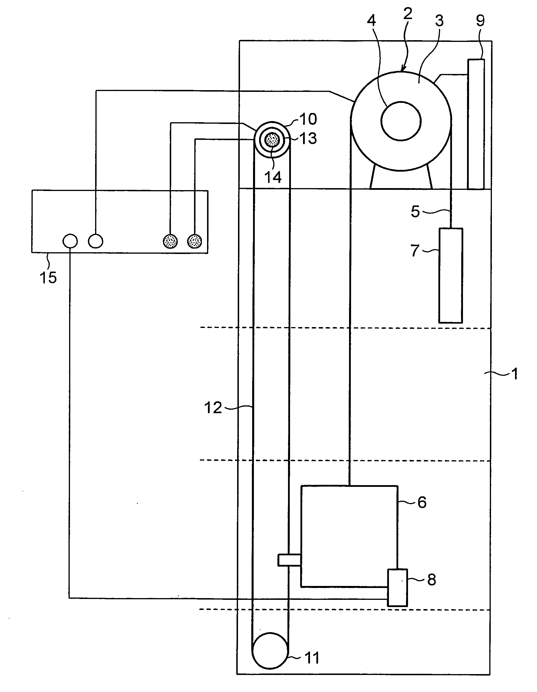
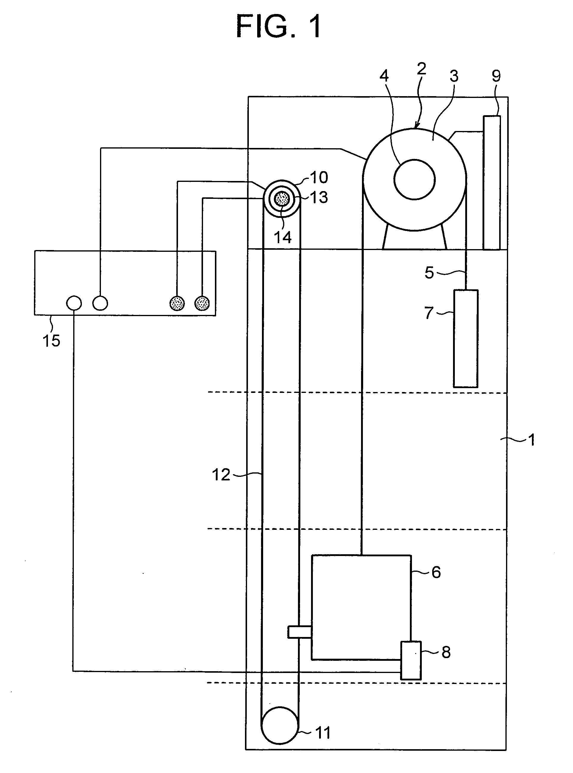
[0025]FIG. 1 is a structural diagram illustrating an elevator apparatus according to Embodiment 1 of the present invention. In the figure, a driving device 2 is disposed in an upper portion of a hoistway 1. The driving device 2 has a driving sheave 3 and a braking device 4 as braking means for braking rotation of the driving sheave 3. A main rope 5 is stretched around the driving sheave 3.

[0026] A car 6 and a counterweight 7 are connected to the main rope 5 and thereby are hung in the hoistway 1. By rotating the driving sheave 3, the car 6 and the counterweight 7 ascend and descend in the hoistway 1. The car 6 has a safety device 8 mounted thereon as braking means for directly braking the car 6. The driving device 2 is controlled by a control panel 9 serving as a controller. The car 6 ascends and descends according to a running speed pattern (an operating speed target value) generated by the control panel 9.

[0027] An upper pulley 10 is disposed in the upper portion of the hoistway...

embodiment 2

[0040] Next, FIG. 4 is a structural diagram illustrating an elevator apparatus according to Embodiment 2 of the present invention, and FIG. 5 is a block diagram illustrating main portions of FIG. 4. In the figures, destination floor buttons 21 for registering a destination floor are provided to a car 6. Landings on respective floors are provided with landing buttons 22. By operating the destination floor buttons 21 or the landing buttons 22, a call is registered in a control panel 9, and the control panel 9 generates a running speed pattern of the car 6. The car 6 ascends and descends according to the running speed pattern generated by the control panel 9.

[0041] The destination floor buttons 21 and the landing buttons 22 are connected to the over speed monitoring portion 15 without the intervention of the control panel 9. More specifically, a call registration signal from the destination floor buttons 21 and the landing buttons 22 is transmitted to the over speed monitoring portion...

embodiment 3

[0055] Next, FIG. 7 is a structural diagram illustrating an elevator apparatus according to Embodiment 3 of the present invention, and FIG. 8 is a block diagram illustrating main portions of FIG. 7. In the figures, a load weighing device 23 for detecting the weight of a car 6 is provided to a connecting portion of a main rope 5 and the car 6. Car weight information from the load weighing device 23 is transmitted to a control panel 9 and overload of the car 6 is detected.

[0056] A running speed pattern generated by the control panel 9 is adjusted based on the car weight information from the load weighing device 23. For example, if the car weight is high, the running speeds in an acceleration region, in a deceleration region, and in a constant speed running region are set to be low. If the car weight is low, the running speeds in the acceleration region, in the deceleration region, and in the constant speed running region are set to be high.

[0057] The load weighing device 23 is also ...


PUM


Abstract

In an elevator apparatus, a car ascends and descends based on a running speed pattern generated by a control panel. Destination floor buttons and landing buttons are connected to an over speed monitoring portion without the intervention of the control panel. The over speed monitoring portion has an over speed setting portion for setting first and second over speeds based on car position information obtained from a car position detector and call registration information obtained from the destination floor buttons and the landing buttons. In the over speed setting portion, a running speed pattern different from the running speed pattern generated by the control panel is independently generated without depending on information from the control panel. The first and second over speeds are set based on the running speed pattern generated by the over speed setting portion.

Description

TECHNICAL FIELD [0001] The present invention relates to an elevator apparatus which has a function of setting an over speed and monitoring whether the running speed of a car reaches the over speed. BACKGROUND ART [0002] For example, in a conventional elevator apparatus disclosed in JP 2003-10468 A, a speed governor monitors whether the running speed of a car reaches an over speed. The speed governor sets, from car running speed pattern information and car call registration information, an over speed which should be judged as abnormal, and compares the actual car running speed and the set over speed. [0003] However, in the conventional elevator apparatus, the speed governor obtains the car running speed pattern information and the car call registration information from a control panel. Therefore, when a runaway car is due to an abnormal control panel, information from the control panel can also be abnormal, and thus, there is a fear that the speed governor cannot detect the over spee...

Claims


Application Information

Patent Timeline
IPC IPC(8): B66B1/28B66B5/06
CPCB66B5/06
Inventor KUGIYA, TAKUOUEDA, TAKAHARUOKAMOTO, KEN-ICHIMATSUOKA, TATSUO
Owner MITSUBISHI ELECTRIC CORP
Why Eureka
Try Eureka