Chassis structure for plasma display module and plasma display module including the chassis structure
Inactive Publication Date: 2006-06-15
SAMSUNG SDI CO LTD
View PDF7 Cites 15 Cited by
Summary
Abstract
Description
Claims
Application Information
AI Technical Summary
This helps you quickly interpret patents by identifying the three key elements:
Problems solved by technology
Method used
Benefits of technology
Benefits of technology
[0013] The present invention provides a chassis structure for plasma display module, which is capable of effectively dissipating heat generated by a plasma display panel and improving assembly of the plasma display module, and a plasma display module including the chassis structure.
Problems solved by technology
However, the chassis of such a plasma display module does not include a heat dissipation structure, and thus, it is difficult to effectively dissipate the heat transmitted to the chassis from the plasma display panel.
Therefore, the number of processes for assembling such a plasma display module is increased, and thus, fabrication of the plasma display module is expensive and time-consuming.
Method used
Image
Click on the blue label to locate the original text in one second.
Reading with bidirectional positioning of images and text.
Examples
first embodiment
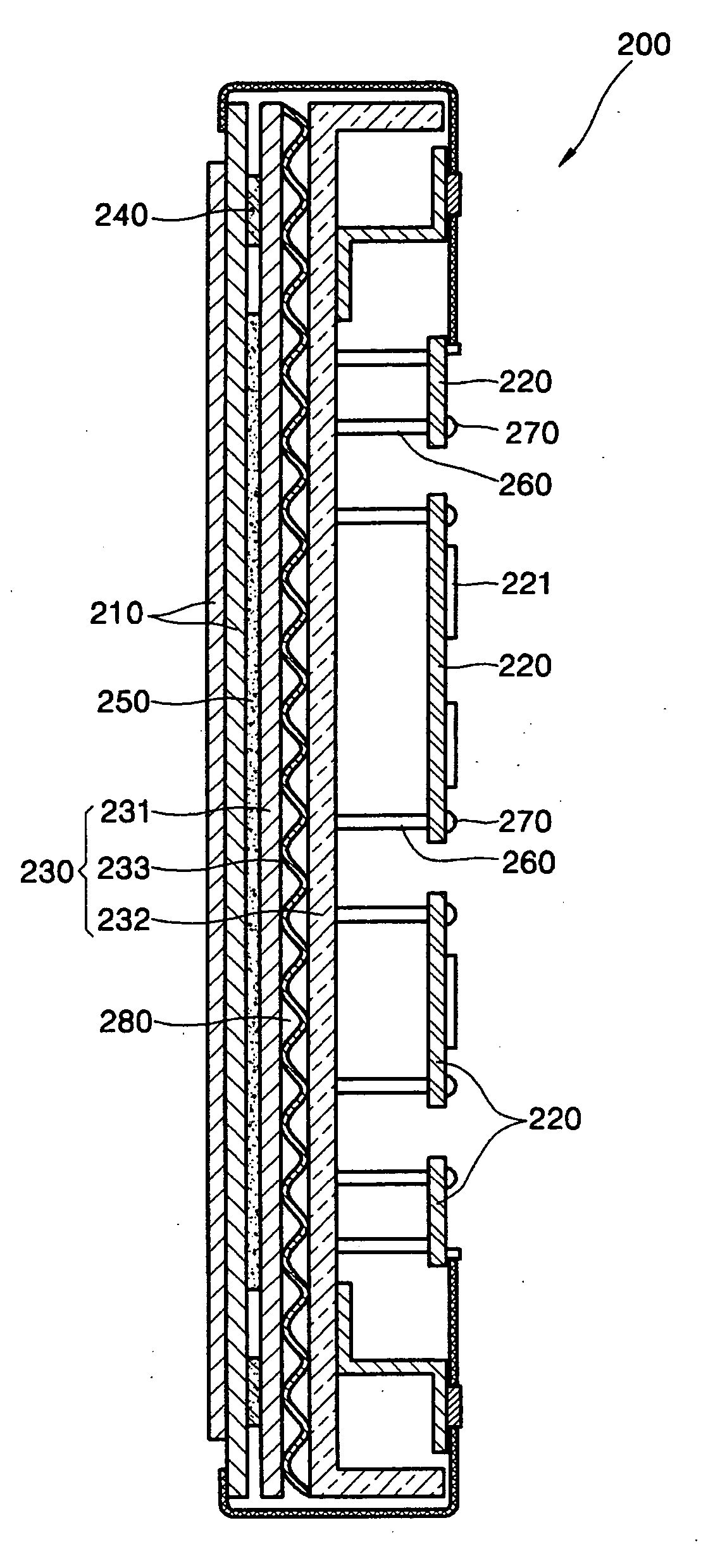
[0039] Referring to FIGS. 3 and 4, a plasma display module 200 according to the present invention includes a plasma display panel 210, a plurality of circuit boards 220, on which circuits for driving the plasma display panel 210 are mounted, and a chassis 230 supporting the plasma display panel 210 and the circuit boards 220.
[0040] The chassis 230 includes a front plate 231, a back plate 232, and a heat dissipation member 233.
[0041] The plasma display panel 210 and the front plate 231 are attached to each other by a dual-adhesive unit 240 affixed to a back surface of the plasma display panel 210, and a circuit device 221 is disposed on the circuit board 220.
[0042] A heat dissipation sheet 250 is disposed between the plasma display panel 210 and the front plate 231 to transmit heat generated by the plasma display panel 210 to the front plate 231.
[0043] The back plate 232 is separated a predetermined distance from the front plate 231, and the predetermined distance can be determine...
second embodiment
[0064] Hereinafter, a plasma display module according to the present invention is described with reference to FIG. 8.
[0065] The plasma display module 500 according to the second embodiment of the present invention includes a plasma display panel 510, a plurality of circuit boards 520, on which circuits driving the plasma display panel 510 are mounted, and a chassis 530 supporting the plasma display panel 510 and the circuit boards 520.
[0066] The chassis 530 includes a front plate 531, a back plate 532, and a heat dissipation member 533.
[0067] The plasma display panel 510 and the front plate 531 of the chassis 530 are attached to each other by a dual-adhesive unit 540 affixed to a back surface of the plasma display panel 510.
[0068] A heat dissipation sheet 550 is disposed between the front plate 531 and the plasma display panel 510 to transmit the heat generated by the plasma display panel 510 to the front plate 531.
[0069] The back plate 532 is separated a predetermined distance ...
PUM
Abstract
A chassis structure for a plasma display module, and a plasma display module including the chassis structure effectively dissipate heat generated by a plasma display panel and improve assembly of the plasma display module. The chassis base includes: a front plate; a back plate separated from the front plate; and a heat dissipation member disposed between the front plate and the back plate, and having a bent cross-section arranged so that some surfaces of the heat dissipation member contact the front plate and some surfaces of the heat dissipation member contact the back plate to allow air flow between the front and back plate.
Description
CLAIM OF PRIORITY [0001] This application makes reference to, incorporates the same herein, and claims all benefits accruing under 35 U.S.C. § 119 from an application for CHASSIS STRUCTURE FOR PLASMA DISPLAY MODULE, AND PLASMA DISPLAY MODULE COMPRISING THE SAME, earlier filed in the Korean Intellectual Property Office on Dec. 10, 2004 and there duly assigned Ser. No. 10-2004-0104035. BACKGROUND OF THE INVENTION [0002] 1. Field of the Invention [0003] The present invention relates to a chassis structure for a plasma display module and a plasma display module including the plasma display module, and more particularly, to a chassis structure for a plasma display panel that effectively dissipates heat generated by a plasma display panel and improves assembly of the plasma display module, and a plasma display module including the chassis structure. [0004] 2. Description of the Related Art [0005] In general, a plasma display panel is a flat panel display apparatus displaying images using ...
Claims
Application Information
Patent Timeline
Application Date:The date an application was filed.
Publication Date:The date a patent or application was officially published.
First Publication Date:The earliest publication date of a patent with the same application number.
Issue Date:Publication date of the patent grant document.
PCT Entry Date:The Entry date of PCT National Phase.
Estimated Expiry Date:The statutory expiry date of a patent right according to the Patent Law, and it is the longest term of protection that the patent right can achieve without the termination of the patent right due to other reasons(Term extension factor has been taken into account ).
Invalid Date:Actual expiry date is based on effective date or publication date of legal transaction data of invalid patent.

