Image pickup module, method of manufacturing the same, and spacer with infrared ray cut film

a pickup module and infrared ray cutting technology, applied in the field can solve the problems of restricted miniaturization of image pickup modules, and achieve the effect of simplifying a manufacturing process and enhancing mass productivity

a pickup module and infrared ray cutting technology, applied in the field can solve the problems of restricted miniaturization of image pickup modules, and achieve the effect of simplifying a manufacturing process and enhancing mass productivity

US20060126194A1Inactive Publication Date: 2006-06-15SHINKO ELECTRIC IND CO LTD

Image

  • Image pickup module, method of manufacturing the same, and spacer with infrared ray cut film
  • Image pickup module, method of manufacturing the same, and spacer with infrared ray cut film
  • Image pickup module, method of manufacturing the same, and spacer with infrared ray cut film

Examples


Embodiment Construction

[0027] Hereinafter, a preferred embodiment of the invention is described in detail with reference to the accompanying drawings.

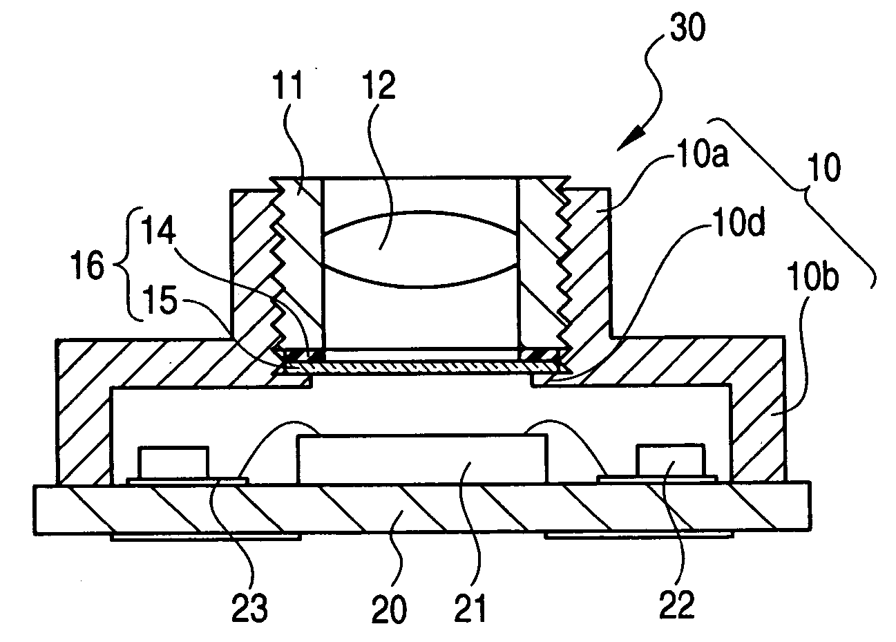
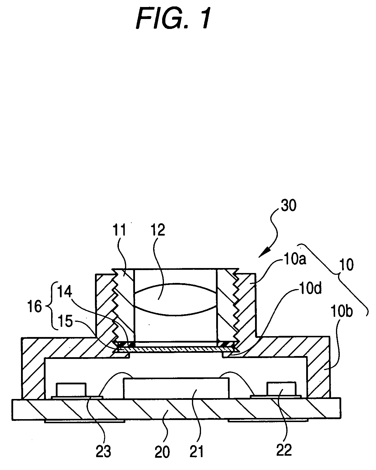
[0028]FIG. 1 shows a configuration of an embodiment of an image pickup module 30 according to the invention. The image pickup module 30 has a holder 10 which supports a light receiving lens 12, and also has a substrate 20 attached to the holder 10. The configurations of a barrel portion 10a and a casing portion 10b of which shape in plan view is rectangular, which configure the body of the holder 10, are similar to those of the holder 10 of the image pickup module of the related art shown in FIG. 5. The configuration of the substrate 20 on which an image pickup element 21 and a chip component 22 are mounted is similar to that of the substrate 20 of the image pickup module of the related art shown in FIG. 5.

[0029] Incidentally, a female screw is provided in an inner circumferential surface of the cylindrically formed barrel portion 10a of the holder 10. A m...


PUM


Abstract

An image pickup module comprises a substrate mounting an image pickup element thereon, a holder mounted on the substrate so as to cover the image pickup element, the holder including a barrel portion for supporting a light receiving lens, the barrel portion having a stopper portion at its inner circumferential surface, a lens holder holding the light receiving lens, the lens holder being screwed and fixed into the barrel portion of the holder, and a spacer interposed between the stopper portion of the holder and the lens holder, the spacer being integrally formed with a sheet-like infrared ray cut film.

Description

[0001] This application claims foreign priority based on Japanese Patent application No. 2004-360998, filed Dec. 14, 2004, the contents of which is incorporated herein by reference in its entirety. BACKGROUND OF THE INVENTION [0002] 1. Field of the Invention [0003] The present invention relates to an image pickup module on which an image pickup element is mounted, for use in an image pickup apparatus, etc., and to a spacer which has an infrared ray cut film, for use in the image pickup module. The present invention also relates to a method of manufacturing the image pickup module. [0004] 2. Description of the Related Art [0005] Various types of products are provided as an image pickup module on which an image pickup element such as a CCD (charge-coupled device) or a CMOS (complementary metal-oxide semiconductor) is mounted (for example, refer to JP-A-2004-147032 and JP-A-2004-235547). FIG. 5 shows an example of an image pickup module configured in such a manner that a light receivin...

Claims


Application Information

Patent Timeline
15 Jun 2006
Publication
US20060126194A1
IPC
G02B7/02; H01L27/14; H04N25/00
CPC
G02B7/006; G02B7/02; H01L27/14618; H01L27/14625; H01L27/14685; H01L31/02164; H04N5/2254; H04N5/2257
Inventors
KAZAMA, YOICHI