Overload protection system for an electrical device

a protection system and electrical device technology, applied in the direction of emergency protective arrangements responsive to undeired changes, motor/generator/converter stoppers, motor/generator/converter control, etc., can solve the problems of affecting the operation of the motor

Active Publication Date: 2006-06-15
CATERPILLAR INC
View PDF11 Cites 23 Cited by
  • Summary
  • Abstract
  • Description
  • Claims
  • Application Information

AI Technical Summary

Problems solved by technology

While these types of motors may be capable of operating for brief periods at peak torque levels greater than their continuous rating, the high currents associated with these peak torque levels can lead to damage of various electric motor components.
For example, a sustained, high-current condition (i.e., an overload condition) may result in elevated temperatures in the conductive windings of the motor stator.
These elevated temperatures can damage the insulation of the windings, which can lead to eventual or even immediate conductor failure.
Monitoring this temperature, however, can be challenging.
Particularly, temperature sensing devices, even if placed directly adjacent to the windings, can provide inaccurate measurements of the winding temperature.
Due to the large mass of metal that may be used to form the motor stator in, especially, heavy duty electric motors for high power traction applications, the motors may have large thermal time constants.
For example, the system includes complex circuitry for measuring the DC voltage and current signals in the motor winding.
This circuitry can add expense to the motor and may adversely affect its reliability.
This can result in added manufacturing expense.
Also, upon detection of an overload condition, the system of the '687 patent fully shuts down the motor rather than allowing the motor to continue operating with a reduced output level.

Method used


Image

  • Overload protection system for an electrical device
  • Overload protection system for an electrical device
  • Overload protection system for an electrical device

Examples


Embodiment Construction

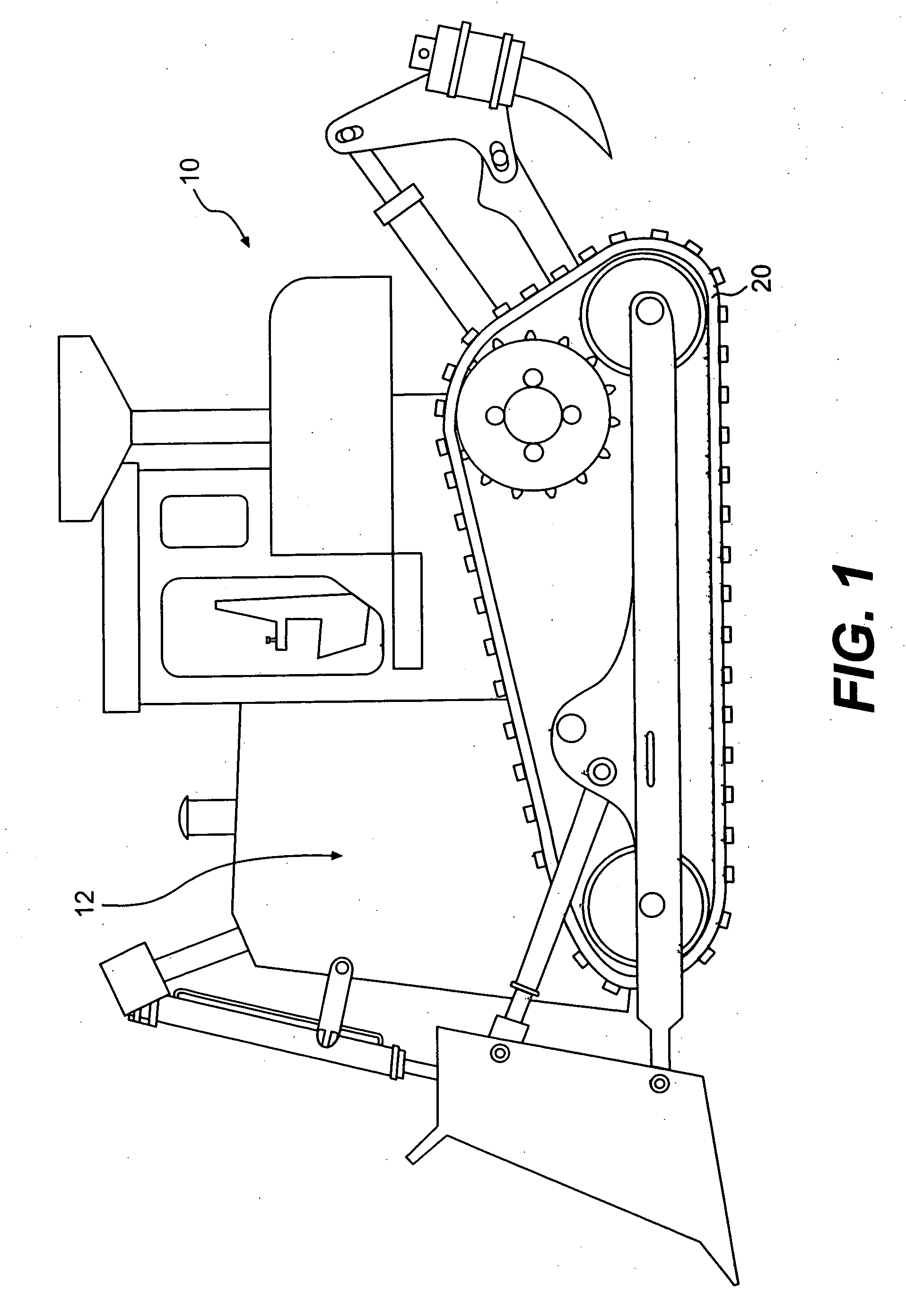
[0015]FIG. 1 provides a diagrammatic perspective view of a work machine 10 according to an exemplary disclosed embodiment. While work machine 10 is illustrated as a track type tractor, work machine 10 may include any type of work machine that includes one or more electric motors. For example, work machine 10 may include on-highway vehicles, off-highway vehicles, wheel loaders, excavators, skid steers, and other types of machinery.

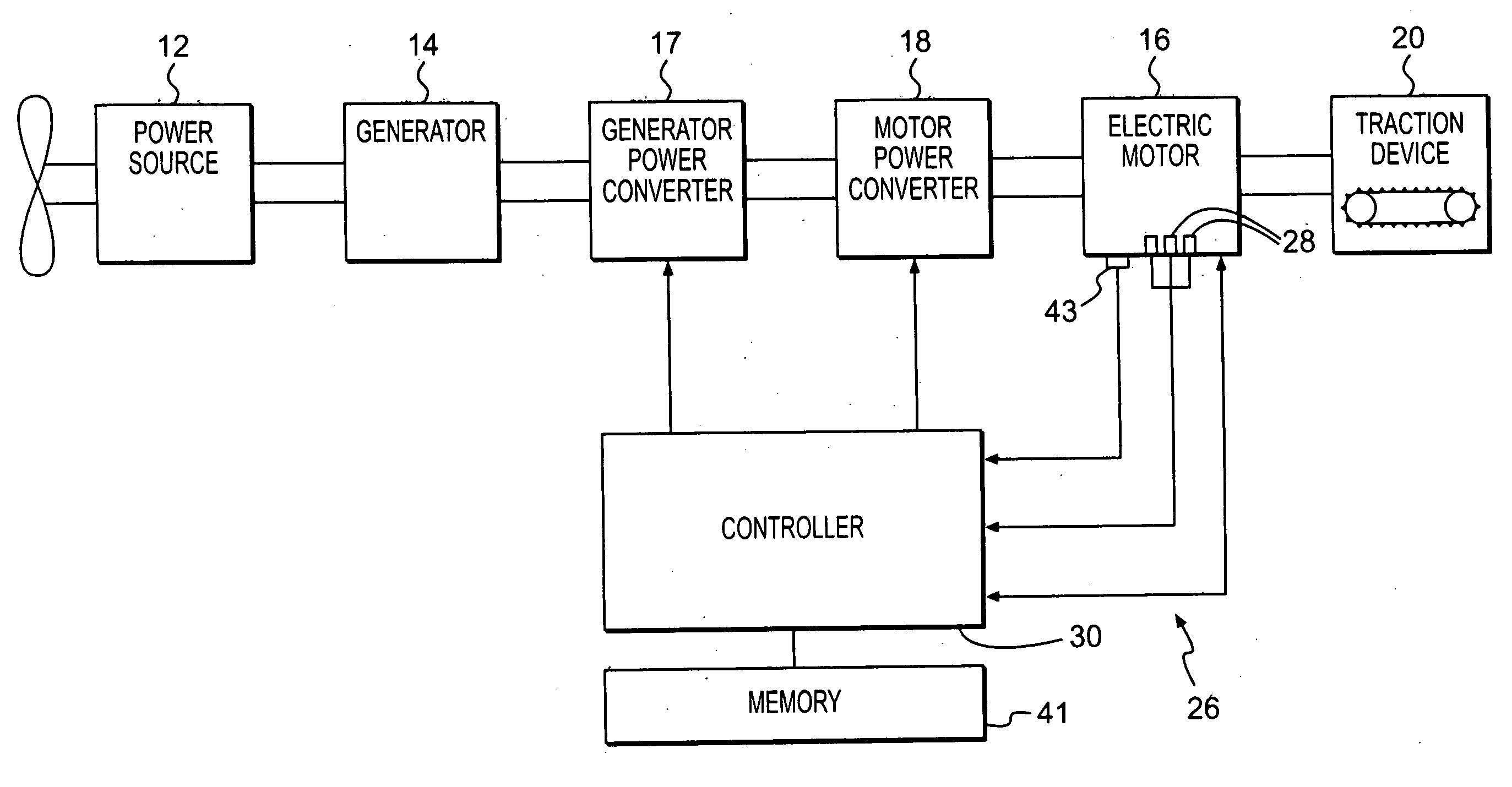
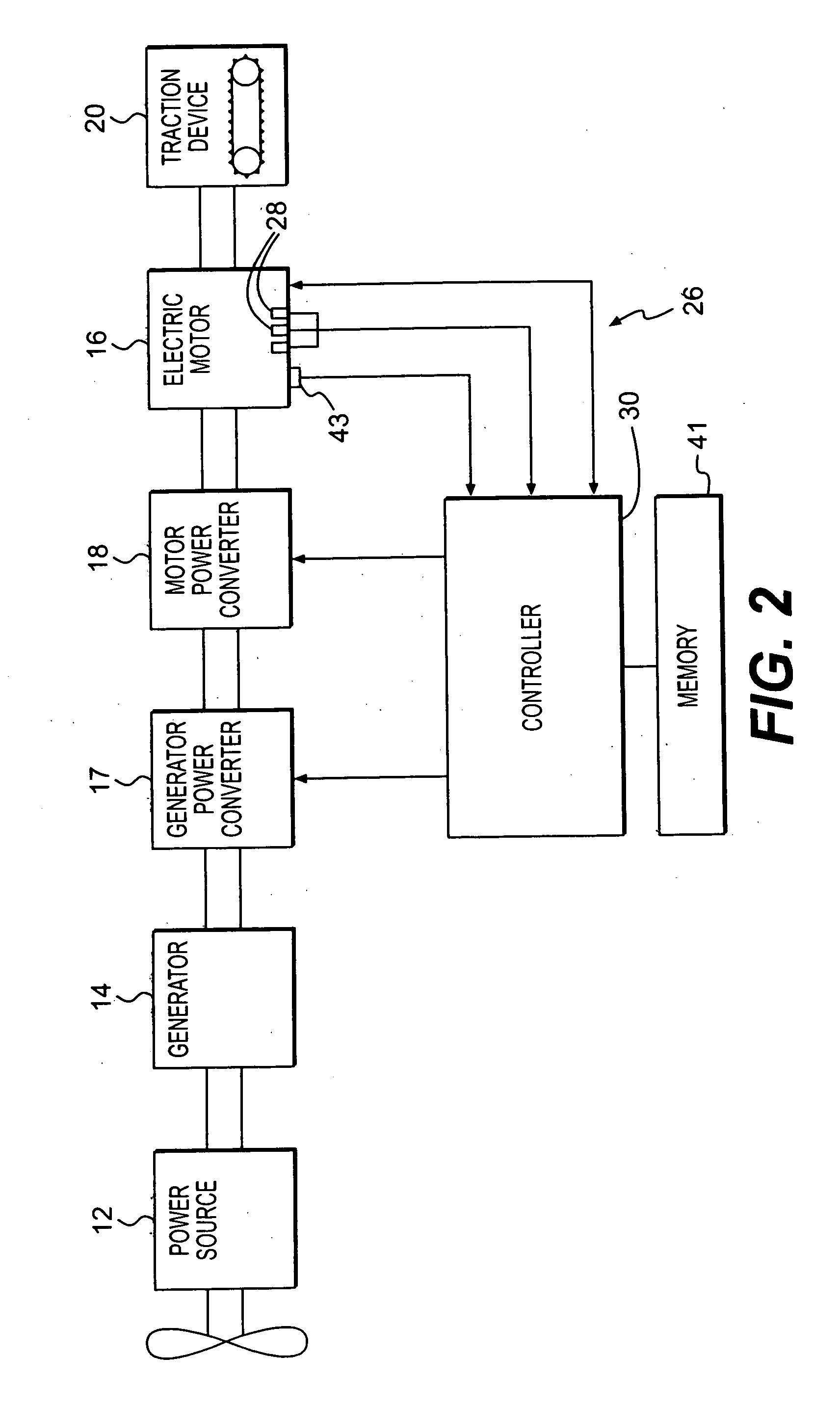
[0016] Work machine 10 may include a power source 12 configured to provide a power output for powering various operations of work machine 10. Power source 12 may include an internal combustion engine that operates using diesel fuel, gasoline, natural gas, or other types of fuel.

[0017] Power source 12 may be operatively coupled to a generator 14, as shown in FIG. 2. Generator 14 may include any type of device that may be configured for converting at least a portion of the power output supplied by power source 12 into electrical energy. For example, in resp...


PUM


Abstract

A protection system for an electrical device may include at least one temperature sensitive element located in a region adjacent to a component of the electrical device and configured to provide an output related to an actual temperature in the region. The system may also include a controller configured to determine the actual temperature in the region based on the output of the at least one temperature sensitive element and to determine a predicted temperature of the component based on the actual temperature in the region and on a predetermined heat dissipation characteristic of the electrical device.

Description

TECHNICAL FIELD [0001] The present disclosure relates to a system for protecting against an overheating condition in an electrical device, and more particularly, to a system for predicting the temperature of windings in an electric motor associated with a work machine and controlling the operation of the electric motor based on the predicted temperature. BACKGROUND [0002] Work machines such as, for example, wheel loaders, track type tractors, and other types of machinery are used for a variety of tasks. These work machines may include a power source, such as a diesel engine, a gasoline engine, a natural gas engine, or any other type of power source, that provides the power required to complete these tasks. In certain power systems, the power source may be coupled to a generator to produce an electrical power output supplied to one or more electric motors. The motors may be connected to ground engaging traction devices to propel the work machine. [0003] The electric motors coupled to...

Claims


Application Information

Patent Timeline
Patent Type & Authority Applications(United States)
IPC IPC(8): H02H5/04
CPCH02H6/005H02H7/085H02P29/0044H02P29/60
Inventor SYCHRA, ROBERT R.STANEK, DANIEL F.TATE, WILLIAM J.
Owner CATERPILLAR INC
Why Eureka
Try Eureka