Method of processing multi-path signals

a multi-path signal and signal processing technology, applied in the field of multi-path signal processing, can solve the problems of performance degradation, rake fingers losing synchronization with multi-path signals on propagation paths,

Inactive Publication Date: 2006-06-15
ALCATEL-LUCENT USA INC +1
View PDF9 Cites 24 Cited by
  • Summary
  • Abstract
  • Description
  • Claims
  • Application Information

AI Technical Summary

Problems solved by technology

. . ) which may cause performance degradation.
By conventional methods, when multi-paths are closely spaced, (e.g., spaced less than one chip period apa

Method used


Image

  • Method of processing multi-path signals
  • Method of processing multi-path signals
  • Method of processing multi-path signals

Examples


example 1

RAKE RECEIVER EXAMPLE 1

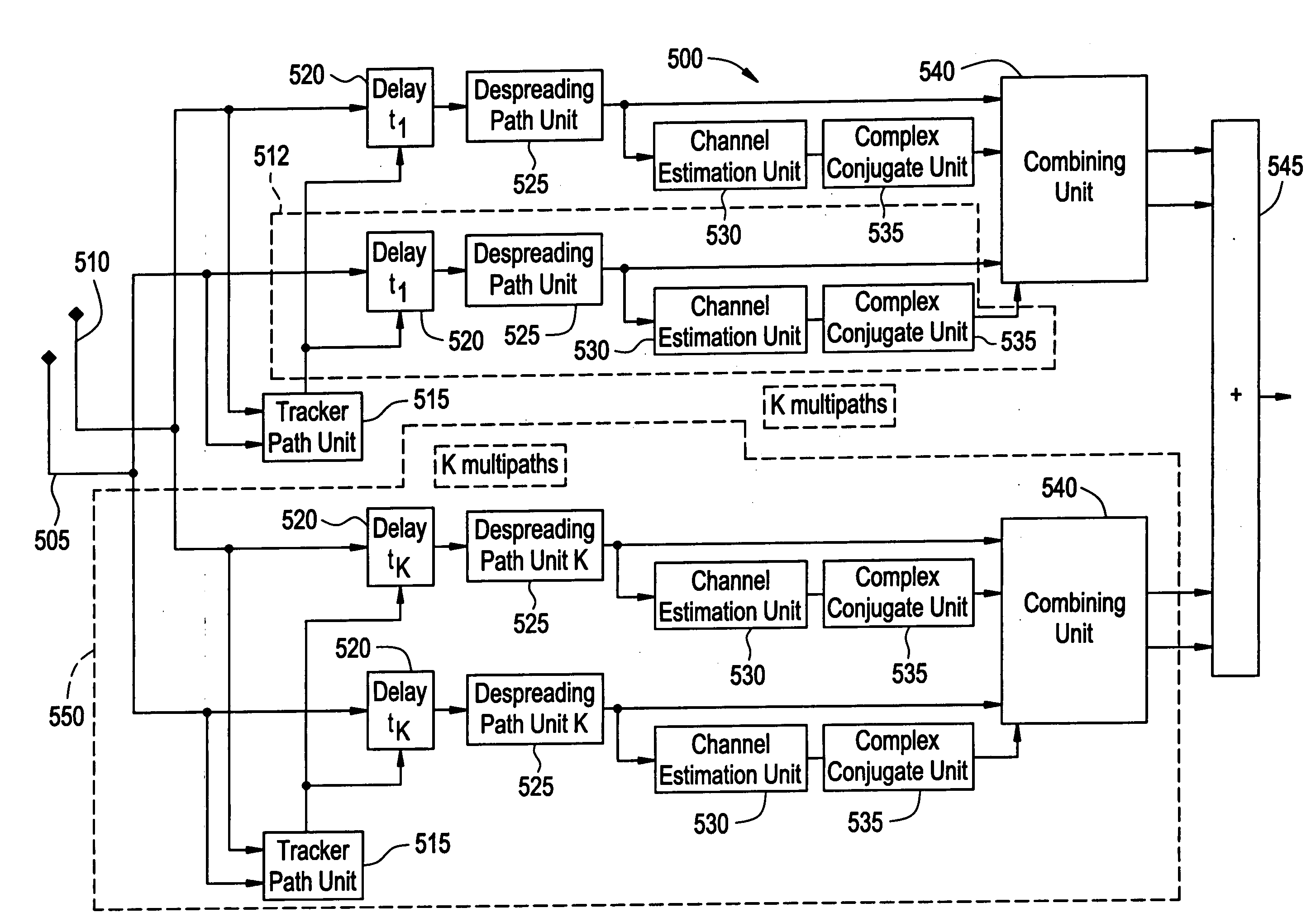
[0016]FIG. 1 illustrates a Rake equalizer structure 500 according to an exemplary embodiment of the present invention. The Rake equalizer structure 500 includes first antenna 505 and second antenna 510. The first and second antennas 505 and 510 are spaced apart from each other by half a wavelength (i.e., λ / 2). It is understood, however, that any separation between first and second antennas 505 / 510 may be used (e.g., greater than λ, less than λ / 2, etc . . . ).

[0017] The rake equalizer structure 500 may include a plurality of tracker path units 515 and delay units 520. In one embodiment, each of the delay units 520 is associated with a given Rake finger. The received antenna signals from each of the first and second antennas 505 / 510 are sent to corresponding tracker path units 515 and delay units 520.

[0018] The Rake equalizer structure 500 may include a plurality of clusters 550, each of the plurality of clusters 550 including a plurality of fingers 512 associ...

example 2

RAKE RECEIVER EXAMPLE 2

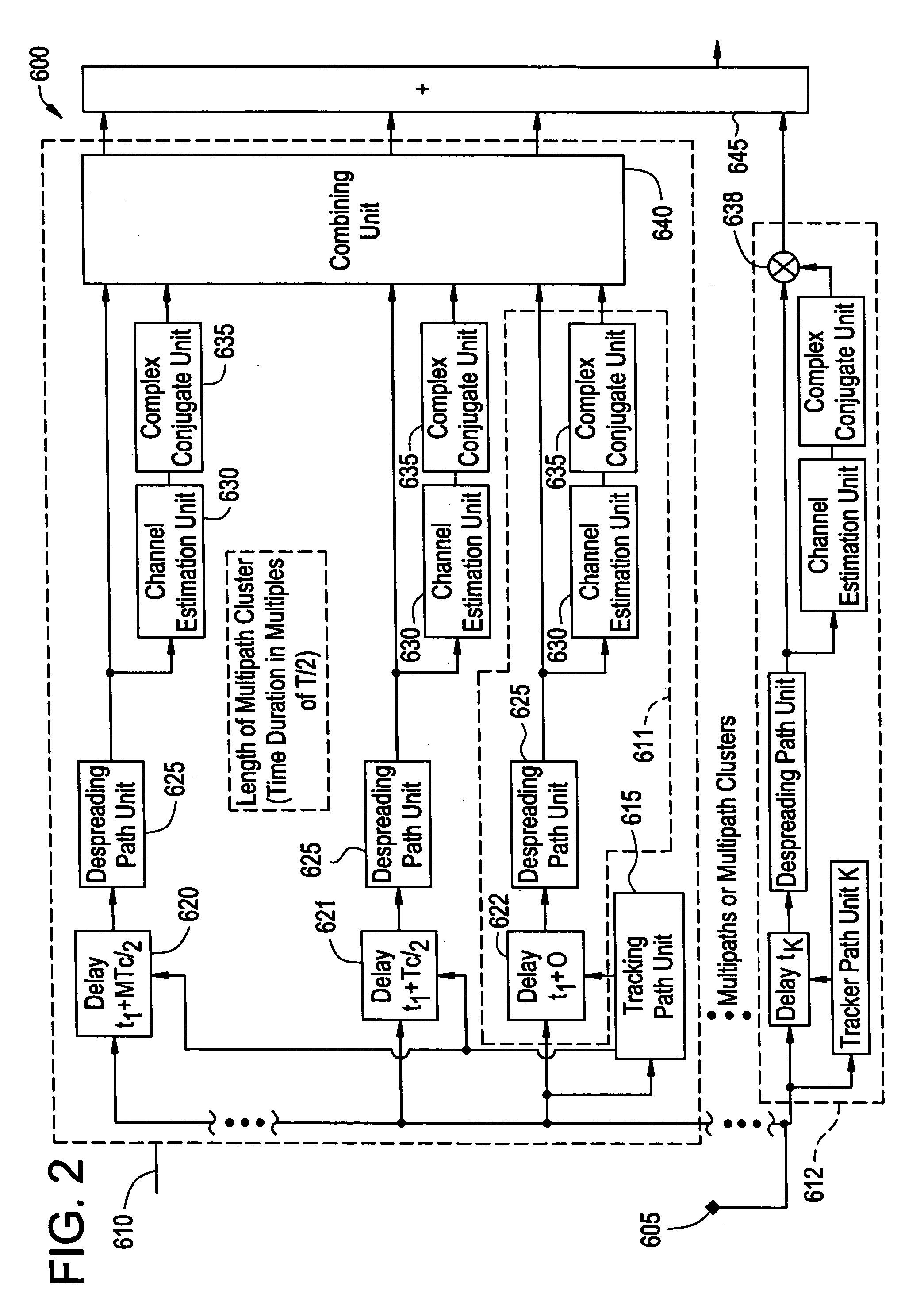
[0023]FIG. 2 illustrates a Rake equalizer structure 600 according to another exemplary embodiment of the present invention. Rake equalizer structure 600 includes a single antenna 605. The Rake equalizer structure includes a plurality of clusters 610, a first plurality of fingers 611 and a second plurality of fingers 612 (e.g., fingers which are not included within a cluster). Each of the plurality of clusters 610 includes a plurality of fingers 612. In one embodiment, a multi-path signal received by a cluster 610 is processed by all of the fingers 611 within the cluster 610. In another embodiment, a multi-path signal sent to a finger 612 not within a cluster is processed only by the finger 612. Each received multi-path signal is sent to either a finger 612 or a cluster 610.

[0024] When a multi-path signal is received at a finger 612 which is not within a cluster 610, the finger 612 may process signals in a similar manner as finger 512 as above-described with r...


PUM


Abstract

In the method of processing signals, multi-path signals are received, channel estimates for the received multi-path signals are determined, and a combining operation is applied to the multi-path signals, the combining operation being a function of a correlation matrix of the received multi-path signals, a correlation matrix of estimates for channels of the received multi-path signals, a cross-correlation matrix of the channels and channel estimates for the received multi-path signals, and the channel estimates.

Description

BACKGROUND OF THE INVENTION [0001] 1. Field of the Invention [0002] The present invention relates generally to a method of processing multi-path signals, and more particularly to a method of processing multi-path signals including a combining operation. [0003] 2. Description of the Related Art [0004] Conventional CDMA receivers typically include Rake receivers. Rake receivers ideally are filters matched to the channel impulse response. In practice, the channel impulse response is not known and an estimate for the channel must be used. The estimation of the channel includes estimation errors (e.g., errors in the signal, errors from noise, etc . . . ) which may cause performance degradation. [0005] By conventional methods, the estimation of the frequency selective channel impulse response may be calculated as a superposition of flat fading multi-path signals. The flat fading multi-path signals may correspond to or be assigned to individual fingers of a conventional Rake receiver. The ...

Claims


Application Information

Patent Timeline
IPC IPC(8): H04B1/707H04L27/06
CPCH04B1/7115H04B1/712
Inventor BACHL, RAINER WALTERKEMPF, ROBERT FRANZ KLAUSPHILIPP, MARKUS EDMUND
Owner ALCATEL-LUCENT USA INC
Why Eureka
Try Eureka