
Image forming apparatus

a technology of image forming apparatus and forming chamber, which is applied in the direction of electrographic process apparatus, instruments, optics, etc., can solve the problems of difficult to predict the number, difficulty in adequately melting toner, and difficulty in predicting the strength of toner, so as to reduce the cooling effect of the cooling device and reduce the waiting time

Active Publication Date: 2006-06-15
OKI ELECTRIC IND CO LTD
View PDF4 Cites 26 Cited by
  • Summary
  • Abstract
  • Description
  • Claims
  • Application Information

AI Technical Summary

Benefits of technology

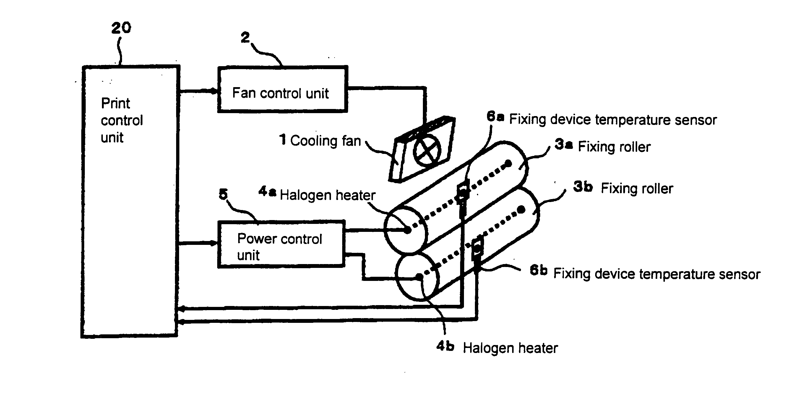
[0012] In order to attain the objects described above, according to the present invention, an image forming apparatus includes a fixing device for fixing developer on a recording medium; a heating device for heating the fixing device; a cooling device for cooling the fixing device; a temperature detecting device for detecting a temperature of the fixing device; a heating device control unit for controlling drive of the heating device; and a cooling device control unit for controlling drive of the cooling device. After the fixing device fixes the developer on the recording medium, when the temperature detecting device detects the temperature of the fixing device below a first temperature, the cooling device control unit controls the cooling device to reduce cooling effect of the cooling device.
[0013] In the invention, after an image forming device forms an image, the cooling device is operated to cool the fixing device. The first temperature is set at a temperature with a specific increment from a lower limit of a printable temperature range per a specific period of time. Accordingly, the cooling device is controlled, so that the temperature of the fixing device gradually approaches to a target temperature. When the temperature of the fixing device becomes below the first temperature, the cooling device is controlled to stop. Accordingly, it is possible to maintain the temperature of the fixing device within the printable temperature range, thereby reducing a waiting time for the next printing operation.

Problems solved by technology

At a temperature below the specific temperature range, it is difficult to adequately melt the toner.
As a result, the toner is stuck to the recording medium with a strength less than a desirable level, and the toner may be stuck to a fixing roller, not the recording medium, a phenomenon called cold off-set.
A target temperature is set, in general, such that the fixing device is heated up to a high temperature as possible, since it is sometimes difficult to predict the number of media.
However, when a target temperature is set such that the fixing device is heated up at a high temperature as possible, and only a small number of media pass through the fixing device, the fixing device is not cooled down.
At this moment, the fixing device may be suddenly heated up above the specific printable temperature range, thereby causing the over-shoot.

Method used


Image

  • Image forming apparatus
  • Image forming apparatus
  • Image forming apparatus

Examples


first embodiment

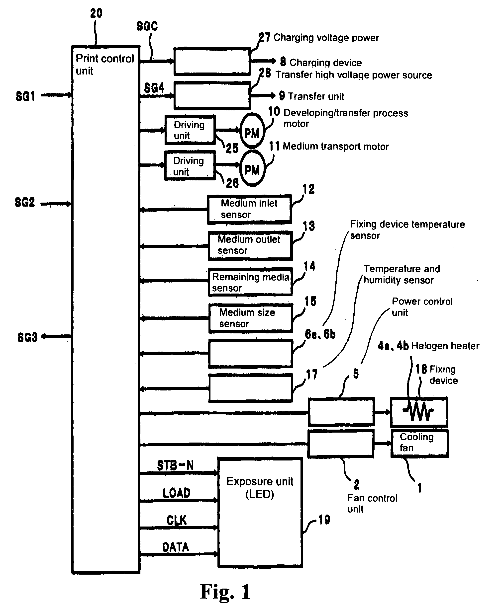
[0032] In the first embodiment, an image forming apparatus is provided with a cooling fan as a cooling device. In the image forming apparatus, a specific temperature condition is set for stopping the cooling fan according to a time after the image forming apparatus completes printing. That is, after the image forming apparatus completes printing, when a temperature of a fixing device becomes below a specific temperature, the cooling fan stops, so that cooling effect of the cooling fan is reduced.

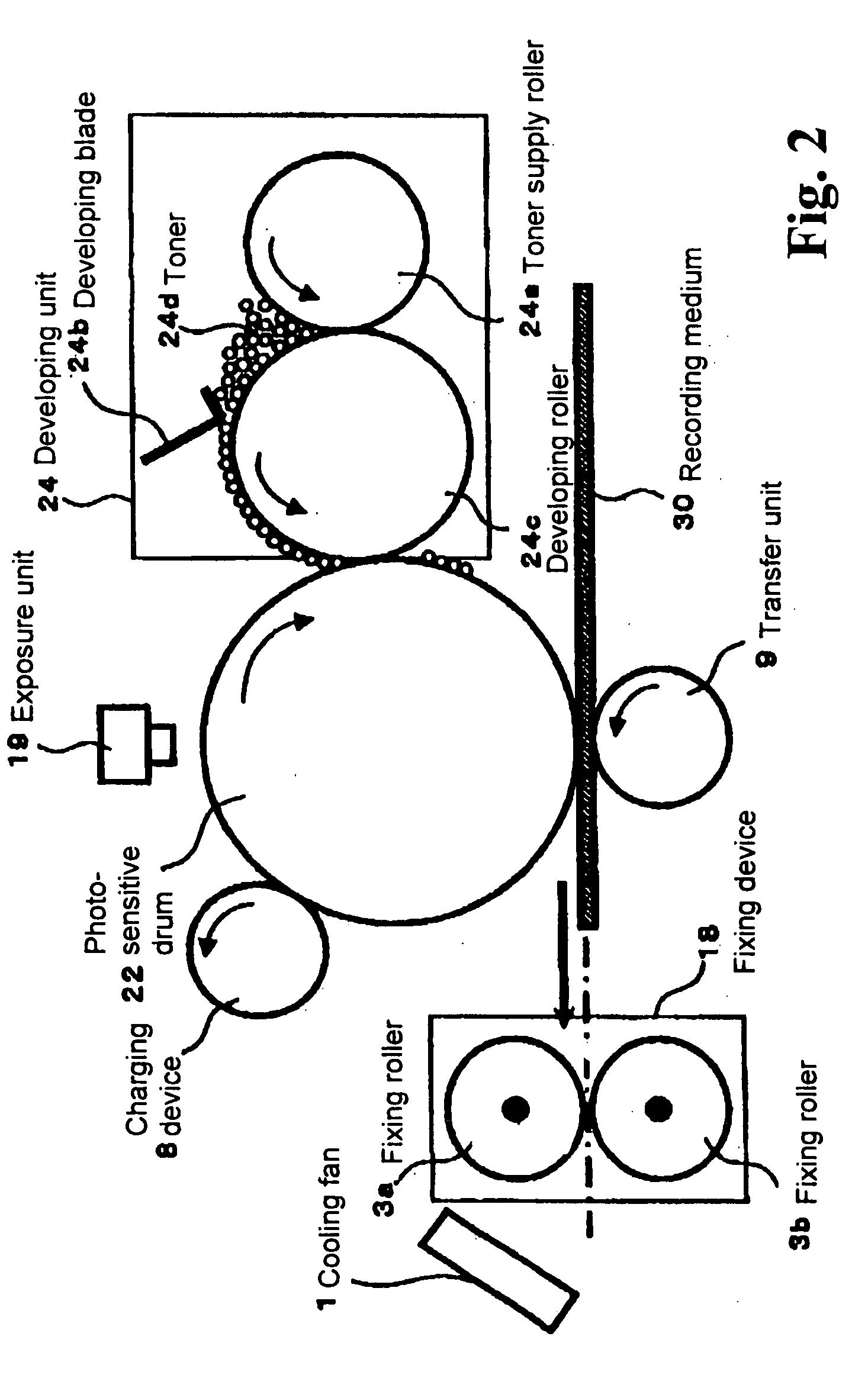
[0033]FIG. 1 is a schematic block diagram of a control system of an image forming apparatus according to a first embodiment of the present invention. FIG. 2 is a schematic view showing a main configuration of the image forming apparatus. The image forming apparatus includes a print control unit 20 for controlling a printing operation; an exposure unit 19 for radiating exposure light according to control of the print control unit 20; a photo-sensitive drum 22 having a photo-sensitive member ...

second embodiment

[0065] In an image forming apparatus according to the second embodiment of the present invention, in addition to the fan stop temperature, a fan resume temperature is set to resume an operation of the cooling fan according to a specific time after the printing is completed. Configurations of the image forming apparatus, the system control thereof, and the fixing device in the second embodiment are the same as those of the image forming apparatus in the first embodiment shown in FIGS. 1 to 3, and explanations thereof are omitted. Also, a printing operation of the image forming apparatus in the second embodiment is the same as that of the image forming apparatus in the first embodiment, and an explanation thereof is omitted.

[0066]FIG. 10 is a time chart showing the operation of the cooling fan according to the second embodiment of the present invention. The horizontal axis represents time t after the printing is completed, and the vertical axis represents the temperature Td of the fi...

third embodiment

[0081] In an image forming apparatus according to the third embodiment of the present invention, a fan acceleration temperature or a fan deceleration temperature is set to accelerate or decelerate a speed of the cooling fan according to a specific time after the printing is completed. Configurations of the image forming apparatus, the system control thereof, and the fixing device in the third embodiment are the same as those of the image forming apparatus in the first embodiment shown in FIGS. 1 to 3, and explanations thereof are omitted.

[0082]FIG. 13 is a schematic view showing a cooling fan control unit 112 according to the third embodiment of the present invention. Only components different from those in the first embodiment will be explained.

[0083] An end of the cooling fan 1 is connected to a power source Vdd and an end of a resistance R3a 110. The other end of the cooling fan 1 is connected to the other end of the resistance R3a 110 and ends of resistances R4a 121, R5a 122, ...


PUM


Abstract

An image forming apparatus includes a fixing device for fixing developer on a recording medium; a heating device for heating the fixing device; a cooling device for cooling the fixing device; a temperature detecting device for detecting a temperature of the fixing device; a heating device control unit for controlling drive of the heating device; and a cooling device control unit for controlling drive of the cooling device. After the fixing device fixes the developer on the recording medium, when the temperature detecting device detects the temperature of the fixing device below a first temperature, the cooling device control unit reduces cooling effect of the cooling device.

Description

BACKGROUND OF THE INVENTION AND RELATED ART STATEMENT [0001] The present invention relates to an image forming apparatus such as an electric-photo printer, a copier, and a facsimile. In particular, the present invention relates to a fixing device of the image forming apparatus. [0002] In a conventional image forming apparatus such as an electric-photo printer, a copier, and a facsimile, a fixing device heats developer transferred to a recording medium to melt, and presses the developer with a specific pressure to fix the same on the recording medium (refer to Patent Reference 1). The fixing device is provided with a heat source for supplying heat necessary for the fixing process. The heat source is controlled to have a temperature within a specific temperature range at which the fixing device can fix the developer. [0003] Within the specific temperature range, developer or toner suitable for the recording medium can be properly fixed. At a temperature below the specific temperature ...

Claims


Application Information

Patent Timeline
Patent Type & Authority Applications(United States)
IPC IPC(8): G03G15/20
CPCG03G2215/20G03G15/2017
Inventor SATO, TOSHIKI
Owner OKI ELECTRIC IND CO LTD
Learn More