Image Forming Apparatus

Inactive Publication Date: 2006-06-15
CANON KK
View PDF1 Cites 4 Cited by
  • Summary
  • Abstract
  • Description
  • Claims
  • Application Information

AI Technical Summary

Benefits of technology

[0012] The object of this invention is to provide an image forming apparatus in which the developer used to form an image is recovered efficiently by a first recovery means without deteriorating the productivity thereby to lengthen the life of the image bearing member and the first recovery means.

Problems solved by technology

The resulting rotation of only the photosensitive drum and the cleaning blade especially made of an elastic body increases the friction force between the photosensitive drum and the blade and deteriorates the smoothness of the cleaning blade.
Once this state is maintained, the problem is caused such as the image flow due to the deterioration of the drum surface, the cut, twist, wear or noise of the blade.
Therefore problems such as generation of a standby time in the operation of the image forming apparatus or reduction in the productivity (number of images formed per unit time) have occurred.

Method used


Image

  • Image Forming Apparatus
  • Image Forming Apparatus
  • Image Forming Apparatus

Examples


first embodiment

[0031] An image forming apparatus according to a first embodiment of the invention is explained.

[Apparatus Configuration and General Operation]

[0032] First, the configuration and the general operation of the apparatus are explained with reference to FIGS. 6 and 7. FIG. 6 is a diagram for explaining the essential parts of the image forming apparatus according to this embodiment, and FIG. 7 a diagram for explaining a processing unit.

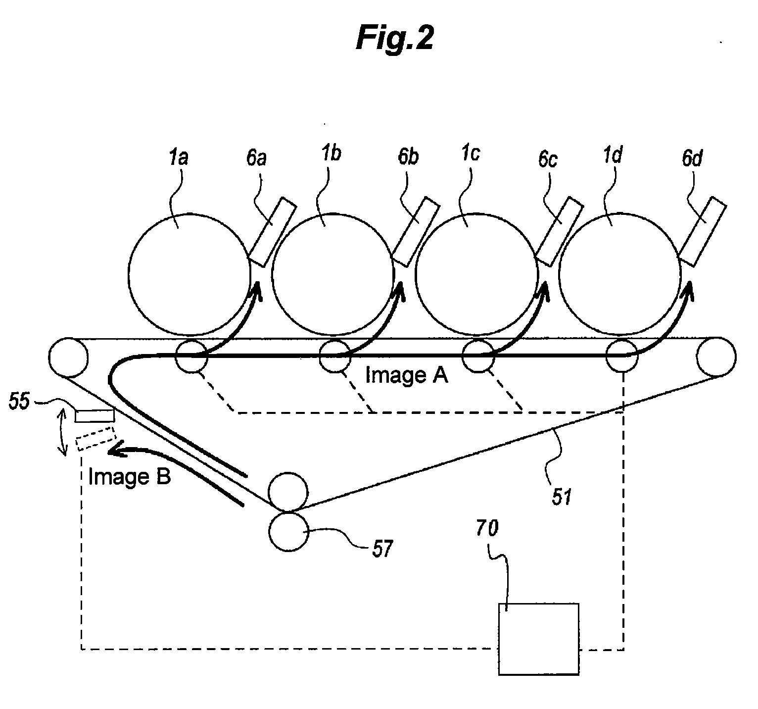
[0033] The image forming apparatus shown in FIG. 6 is a full-color electrophotographic image forming apparatus including four photosensitive drums 1a to 1d as an image bearing member and an intermediate transfer belt (intermediate transfer member) 51 as a transfer medium. Around the photosensitive drums 1a to 1d, there are arranged chargers 2a to 2d, exposure units 3a to 3d, development units 4a to 4d, photosensitive member cleaners 6a to 6d, and the like, each of which make up a processing unit Pa to Pd constituting an image forming means. Images (deve...

second embodiment

[0056] An image forming apparatus according to a second embodiment of the invention is explained. This embodiment is so configured that the belt cleaner 55 recovers the remaining toner electrostatically using a brush in place of the elastic blade separable from the belt.

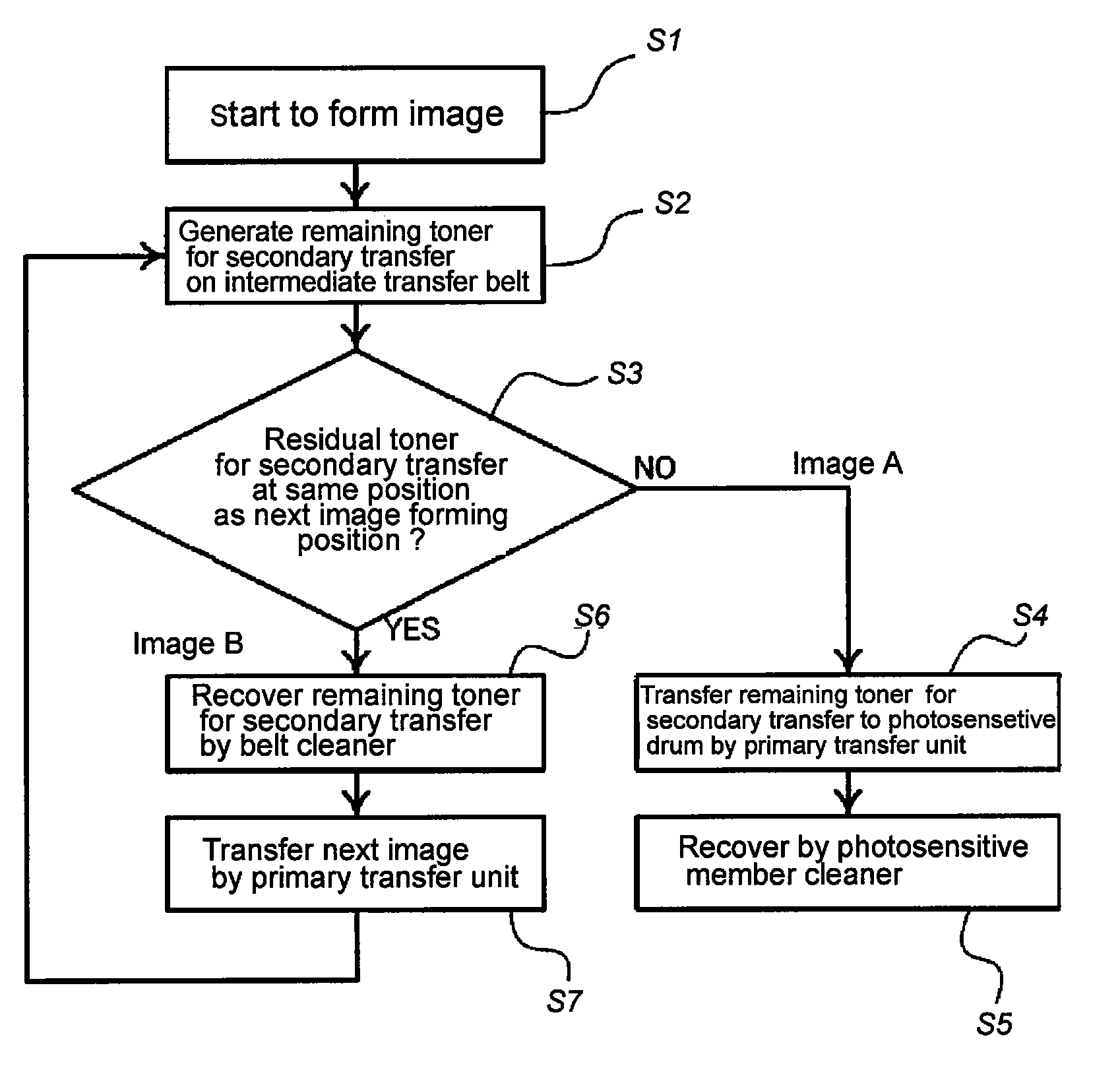
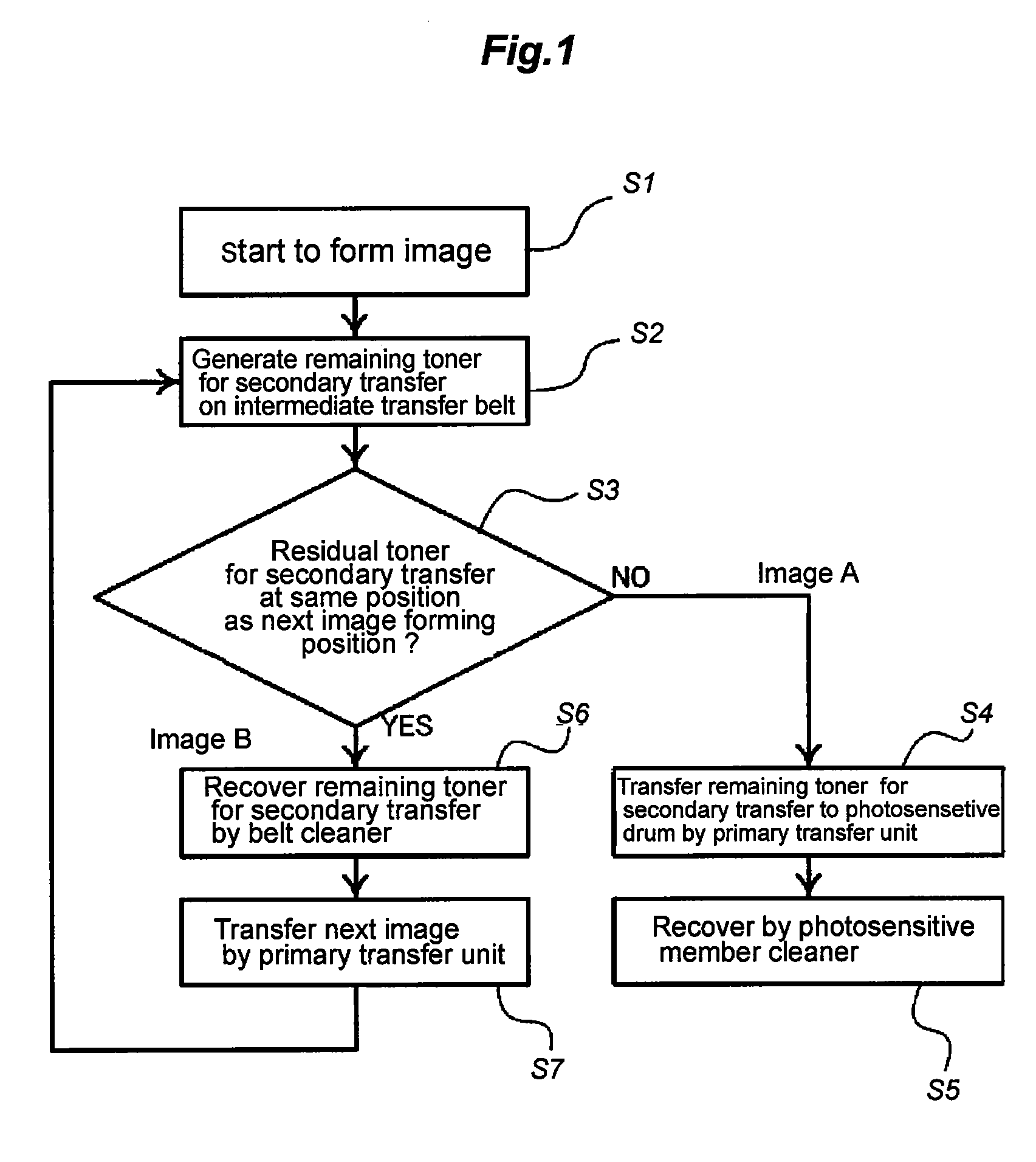
[0057] With the cleaner having the brush, the remaining toner can be recovered by applying a bias of the opposite polarity to the remaining toner. By applying a bias of the same polarity as the remaining toner, on the other hand, the remaining toner can be prevented from being recovered by the brush. Then, the remaining toner can be conveyed as it is to the primary transfer unit N1 through the belt cleaner 55. In the primary transfer unit N1, a bias is applied with such a polarity as to transfer the remaining toner to the photosensitive drum 1. The determination means 70 determines whether the toner on the intermediate transfer belt 51 is to be recovered by the belt cleaner 55 or the photosensitive drum 1.

[0058] Sp...

third embodiment

[0059] An image forming apparatus according to a third embodiment of the invention is explained. FIG. 5 is a timing chart for explaining the movement of the toner image in the primary transfer unit, the secondary transfer unit and the belt cleaning unit 3 according to this embodiment. This timing chart is explained by designating the same component parts as those in the first embodiment by the same reference numerals, respectively.

[0060] In the first embodiment described above, the select operation is performed to determine whether the developer on the transfer medium is to be recovered by the second recovery means or the first recovery means through the image bearing member in accordance with the image formation timing. According to this embodiment, in contrast, the remaining toner remaining on the intermediate transfer belt 51 after the transfer operation is basically recovered by the photosensitive member cleaner 6, while the timing of the next image forming session is changed. ...


PUM


Abstract

An image forming apparatus comprises an image bearing member on which an electrostatic image is formed, a development unit which develops the electrostatic image formed on the image bearing member using a developer and forms a developer image, a first transfer member which transfers the developer image on the image bearing member to an intermediate transfer member by a first transfer unit, a first recovery member which recovers the developer on the image bearing member, a second transfer member which transfers the developer image on the intermediate transfer member to a transfer material at a second transfer position, and a second recovery member which recovers the developer on the intermediate transfer member. The developer on the intermediate transfer member can be recovered by the second recovery means or by the first recovery member though the image bearing member, and the developer image can be continuously transferred to a plurality of transfer materials. The image forming apparatus further comprises a means which determines at the time of continuous transfer of the developer image to the plurality of the transfer materials, whether the developer on the intermediate transfer member is to be recovered by the second recovery member or by the first recovery member through the image bearing member, based on at least the time interval of sessions of developer image transfer to the transfer materials.

Description

BACKGROUND OF THE INVENTION [0001] 1. Field of the Invention [0002] This invention relates to an image forming apparatus for transferring a developer image to a transfer material from an image bearing member through a transfer medium. [0003] 2. Description of the Related Art [0004] An image forming apparatus having a development means in which an electrostatic latent image formed on the surface of a photosensitive drum constituting an image bearing member is developed by the toner in a powder developer is widely put into practical use. FIG. 8 is a diagram for explaining the essential parts of the conventional image forming apparatus. The image forming apparatus shown in FIG. 8 is a full-color electrophotographic image forming apparatus having at least one (for example, four) photosensitive drum 1 as an image bearing member and an intermediate transfer belt 51 as a transfer medium. Around the photosensitive drum 1, a charger 2, an exposure unit 3, a development unit 4, a photosensiti...

Claims


Application Information

Patent Timeline
IPC IPC(8): G03G15/16
CPCG03G15/161G03G21/0011G03G2215/1661G03G2221/001G03G2221/1627G03G21/105G03G15/1605G03G21/0076
Inventor OTA, MITSUHIRO
Owner CANON KK
Why Eureka
Try Eureka