Imprint manufacture method

Inactive Publication Date: 2010-06-15
HITACHT MAXELL LTD
View PDF14 Cites 4 Cited by
  • Summary
  • Abstract
  • Description
  • Claims
  • Application Information

AI Technical Summary

Benefits of technology

[0019]Accordingly, in order to solve the above disadvantages, it is an exemplified object of the present invention to provide an imprint method and apparatus, which lengthen the mold's life. Another exemplary object is to provide an imprint method and apparatus, which provide high-quality processing to an object.

Problems solved by technology

This imprint method can reduce the applied pressure during transferring and lengthen the mold's life because of the compressed gas or supercritical fluid softening step.

Method used


Image

  • Imprint manufacture method
  • Imprint manufacture method
  • Imprint manufacture method

Examples


first embodiment

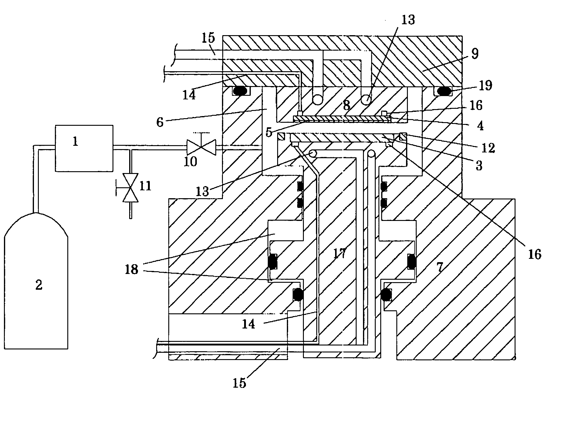
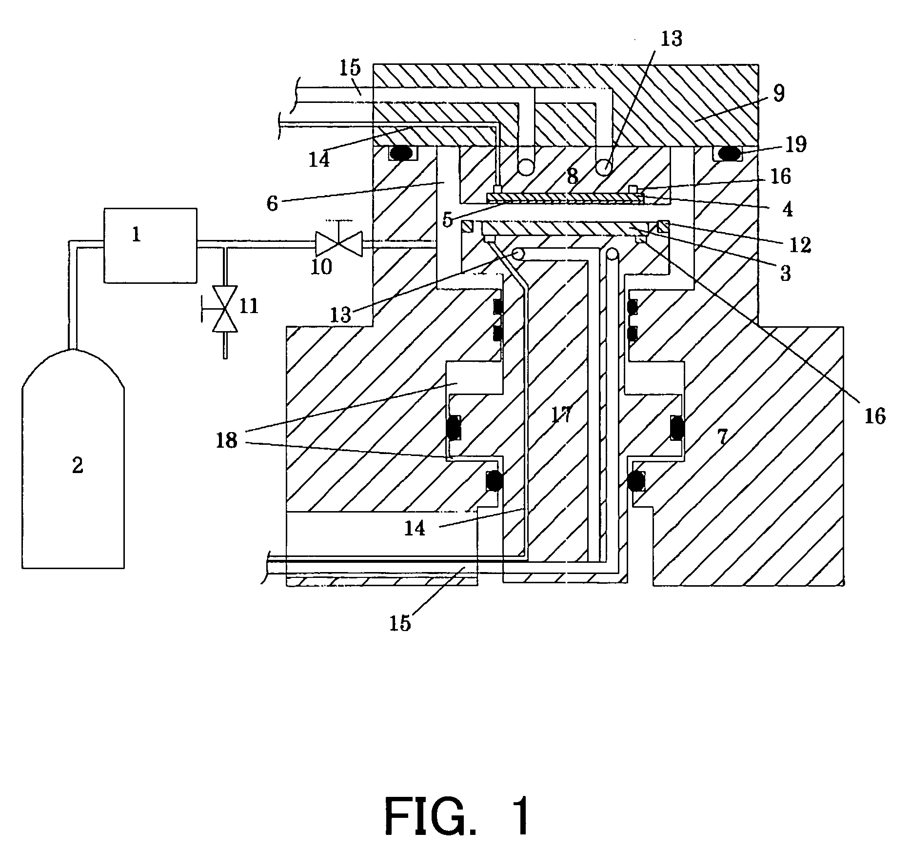
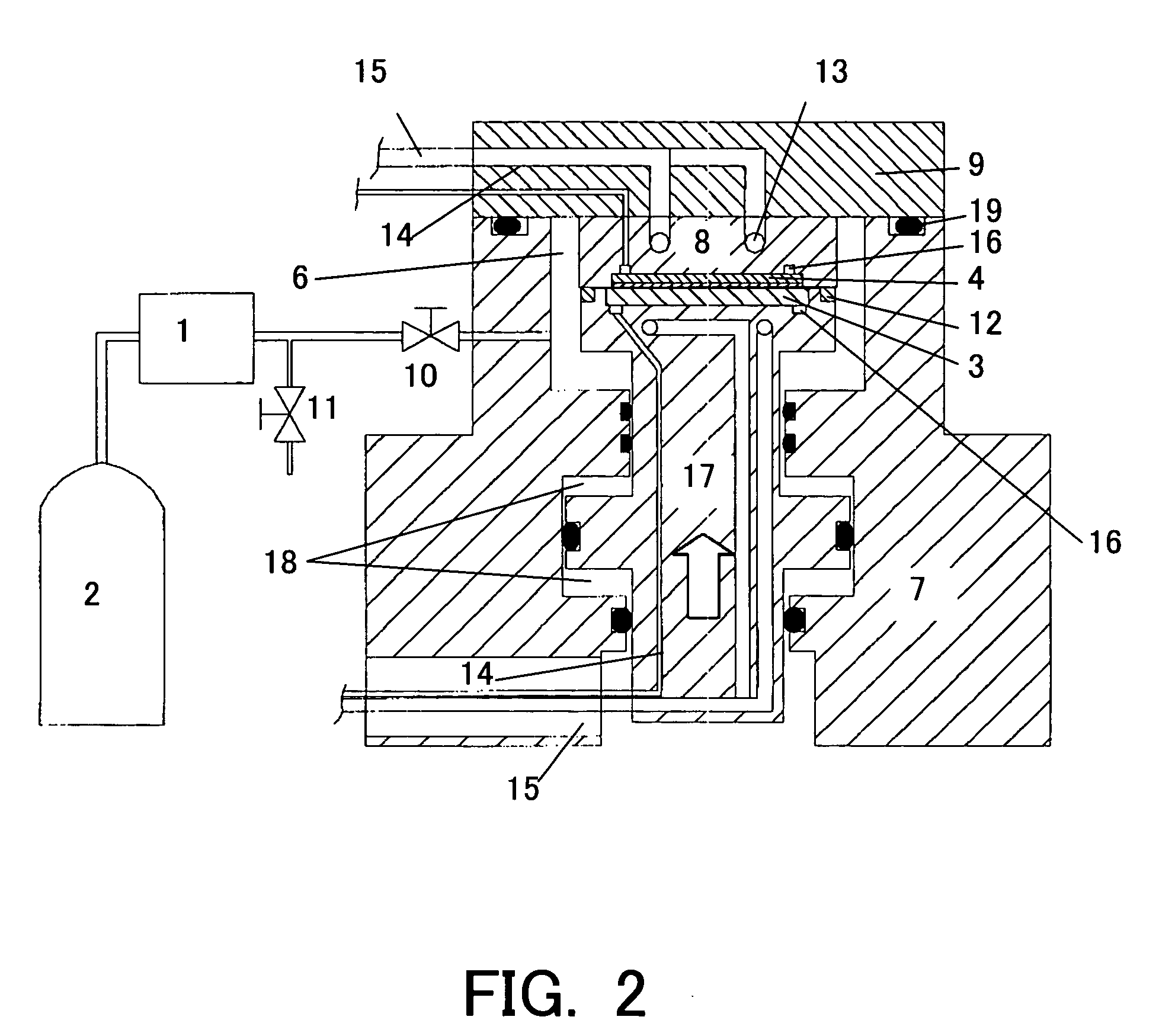
[0060]FIG. 1 shows an NIL apparatus for use with the first embodiment. This embodiment presses a mold 3 having fine convex and concave patterns against a polymer membrane 5 as resist on a substrate 4, such as silicon wafer and quartz glass, while bringing high-pressure CO2 or supercritical CO2 into contact with the polymer membrane 5, and thereby transfers the fine pattern onto the polymer membrane 5.

[0061]This embodiment fills a closed chamber 6 with supercritical CO2 and uses an apparatus that presses in the chamber 6. CO2 gas supplied to a supercritical fluid generator 1 from a CO2 tank 2 enters a supercritical state and is then supplied to the outside by the opening and closing of a built-in electromagnetic valve. Supercritical CO2 can have arbitrary pressure and temperature, but higher pressure would preferably increase infiltration into solid polymer and lower Tg, viscosity and surface tension. However, excessively high pressure would cause difficulties in closing and sealing,...

second embodiment

[0074]FIG. 3 shows a NIL apparatus for use with the second embodiment. This embodiment presses a mold 300 having fine convex and concave patterns against resist (polymer membrane) 200 on a substrate 100, such as silicon wafer and quartz glass, while bringing high-pressure CO2 or supercritical CO2 into contact with the resist 200, thereby transferring a fine pattern onto the polymer membrane.

[0075]For an easy design of a pressure container, the present invention prefers the use of compressed CO2 or supercritical CO2 for filling the pressure chamber. This embodiment forms the high-pressure chamber as an outer ring 110 outside a glass substrate 100 contacts a piston 270. High-pressure CO2 introduced through a channel 320 moves up the outer ring 110. Even when the substrate 100 does not contact the mold 300, such as a stamper, an O-ring 120 contacts the piston 270 and maintains the high-pressure gas in the chamber.

[0076]A description will be given of the press mechanism of the instant e...

third embodiment

[0093]The imprint method similar to that of the first embodiment introduced silicon oil (with a molecular weight of 1000) as water repellency agent into the reserve tank 250, dissolved it in supercritical CO2, and infiltrated it into the resist 200. The third embodiment improved release characteristics between the mold 300 and the resist 200, whereby the substrate 100 does not stick to the mold 300 and / or there was no transferring problem.

[0094]Further, the present invention is not limited to these preferred embodiments, and various variations and modifications may be made without departing from the scope of the present invention. For example, these embodiments used compressed CO2 or supercritical CO2, but the present invention does not limit the compressed gas or supercritical fluid to CO2 and may use compressed He, supercritical He, or the like.


PUM

PropertyMeasurementUnit
Lengthaaaaaaaaaa
Pressureaaaaaaaaaa
Pressureaaaaaaaaaa

Abstract

Provided is an imprint method that includes the steps of softening resist in an object to be processed, by using compressed gas or supercritical fluid, the object including a substrate and the resist applied onto the substrate, and transferring a predetermined pattern onto the resist by pressing a mold that forms the predetermined pattern against the resist in the object.

Description

[0001]This application claims the right of priority under 35 U.S.C. §119 based on Japanese Patent Application No. 2003-1171, filed on Jan. 7, 2003, which is hereby incorporated by reference herein in its entirety as if fully set forth herein.BACKGROUND OF THE INVENTION[0002]The present invention relates to an imprint manufacture method and apparatus, a magnetic recording medium, and its manufacture apparatus.[0003]The fine patterning technology for semiconductor manufacture has developed remarkably. The currently required and available critical dimension processing accuracy is 100 nm or smaller. Fine patterning technologies onto resist on a silicon wafer have used photolithography, direct imaging using an electron beam, and the like. Photolithography has improved the resolution with a shortened wavelength of a light source, but the exposure apparatuses are very expensive and transferring a pattern of 100 nm or smaller is difficult. On the other hand, the direct imaging using an elec...

Claims


Application Information

Patent Timeline
IPC IPC(8): B29C43/56B29B13/00C03C17/00
CPCC03C17/002B29C43/021C03C2218/355B29C2043/025
Inventor YUSA, ATSUSHISUGIYAMA, TOSHINORI
Owner HITACHT MAXELL LTD
Why Eureka
Try Eureka