Flame resistant composite structure

Inactive Publication Date: 2014-01-23
HEXION INC
View PDF5 Cites 3 Cited by
  • Summary
  • Abstract
  • Description
  • Claims
  • Application Information

AI Technical Summary

Benefits of technology

This patent is about a method for making things like pressure vessels and storage vessels using an epoxy composite. A layer of phenolic resin is applied to the surface of the vessel and serves as a tool for the epoxy when it is applied. This process makes the production faster and more efficient. The added layer of phenolic resin also helps the vessel expand and contract without getting damaged. Furthermore, it acts as a thermal barrier and makes the vessel safer in case of fire.

Problems solved by technology

One disadvantage of such vessels and / or composite structures, especially those prepared with epoxy composites, is that they have very low flame resistance.
While this is effective in reducing the flammability of the composite, it has the disadvantage of increasing the density of the material and in turn increasing the weight of the resulting structure.
This negates much of the benefit of using a fiber reinforced composite.
Additionally, imparting flame retardancy by the use of inorganic additives such as antimony, alumina, magnesium, and boron compounds additionally adds significant density to the matrix resin and creates issues with processing such as creating homogenous dispersions.
However, these hydrates of salts have a high density and add significant weight to the article.
This also poses processing challenges such as adding to the viscosity and settling out of the resin.

Method used


Image

  • Flame resistant composite structure
  • Flame resistant composite structure

Examples


example 1

Phenolic Resin Coated Epoxy Composite Material

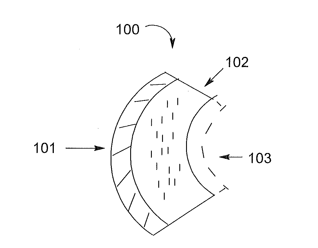
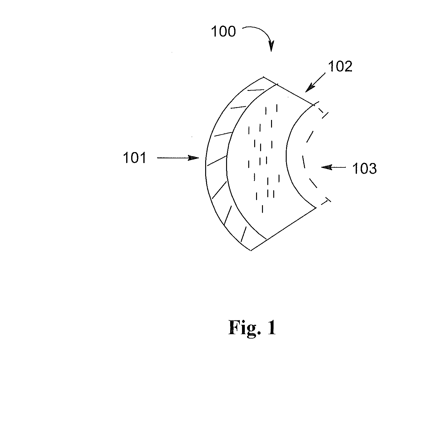
[0056]Samples of the phenolic resin coated epoxy composite material were prepared as follows. The phenolic material of Cellobond FRP J2027L was blended with Cellobond Phencat 10 catalyst as 100 parts of phenolic resin and 10 parts catalyst. The mixed phenolic material was then poured into the plastic tube. The epoxy composite panel was placed in the plastic tube and the mixed phenolic material was disposed on the epoxy composite panel. The epoxy composite panel was exposed to the mixed phenolic material for thirteen minutes and allowed to dry for three hours. The epoxy composite panel was then placed again in the plastic tube and a second coat of the mixed phenolic material was disposed on the epoxy composite panel. The epoxy composite panel was then cured for 72 hours at ambient conditions.

example 2

Fiber Reinforced Phenolic Layered Epoxy Composite Material

[0057]Samples of the fiber reinforced phenolic resin coated epoxy composite material were prepared as follows. A 7″ long sleeve was made from the thin woven fiberglass and then an epoxy composite panel was placed into the sleeve. The phenolic material of Cellobond FRP J2027L was blended with Cellobond Phencat 10 catalyst as 100 parts of phenolic resin and 8 parts catalyst. The mixed phenolic material was then poured into the plastic tube. The sleeved epoxy composite panel was placed in the plastic tube and the mixed phenolic material was disposed on the sleeved epoxy composite panel. The sleeved epoxy composite panel was exposed to the mixed phenolic material for thirteen minutes and allowed to dry for three hours. The epoxy composite panel was then placed again in the plastic tube and a second coat of the mixed phenolic material was disposed on the sleeved epoxy composite panel. The resulting epoxy composite panel was then c...


PUM


Abstract

Composites and methods for manufacturing composites are provided herein. In one embodiment, a composite structure is provided including a resin composite material and a surface layer disposed on the resin composite material, wherein the surface layer comprises a phenolic resin. In another embodiment, a vessel comprising a composite overwrapped vessel may be improved in regard to high temperature performance by applying thereto a surface layer comprising a phenolic resin.

Description

RELATED APPLICATION DATA[0001]This application claims benefit to U.S. Provisional Application No. 61 / 672,601, filed Jul. 17, 2012, which the entire content of the application is incorporated by reference herein.BACKGROUND OF THE INVENTION[0002]1. Field of the Disclosure[0003]The invention relates to composites, methods for manufacturing the composites, and articles constructed from the composites.[0004]2. Background of the Disclosure[0005]High-performance fibers combined with thermoset or thermoplastic resins offer very high strength-to-weight ratios and are ideal for making lightweight storage vessels, pressure vessels and other composite structures and articles. Such vessels, for example, may have very thin walls, but can still be quite strong.[0006]One disadvantage of such vessels and / or composite structures, especially those prepared with epoxy composites, is that they have very low flame resistance. Historically, flame retardancy has been imparted to such composites by incorpor...

Claims


Application Information

Patent Timeline
IPC IPC(8): C09D5/18
CPCC09D5/18C08K7/14C09D161/16C08J2361/06C08J2463/00C08J7/0427C09K21/14C09D161/04Y10T428/31942Y10T428/31786Y10T428/31594
Inventor LOY, TERRY D.
Owner HEXION INC
Why Eureka
Try Eureka