Fuel containment and recycling system

Inactive Publication Date: 2006-06-15
FARIS SADEG M
View PDF1 Cites 31 Cited by
  • Summary
  • Abstract
  • Description
  • Claims
  • Application Information

AI Technical Summary

Benefits of technology

[0009] In view of the above, it is an object of the present invention to provide a convenient, economical and

Problems solved by technology

Since oxygen is readily available in the air, it is usually unnecessary to utilize a dedicated oxygen storage vessel for the fuel-cell battery (except in certain configurations where there the oxygen supply is limited due to design considerations).
These systems never achieved any commercial success because they all had relatively low power output (acceptable drain rates and overall capacities).
Until now, this has bee

Method used


Image

  • Fuel containment and recycling system
  • Fuel containment and recycling system
  • Fuel containment and recycling system

Examples


first embodiment

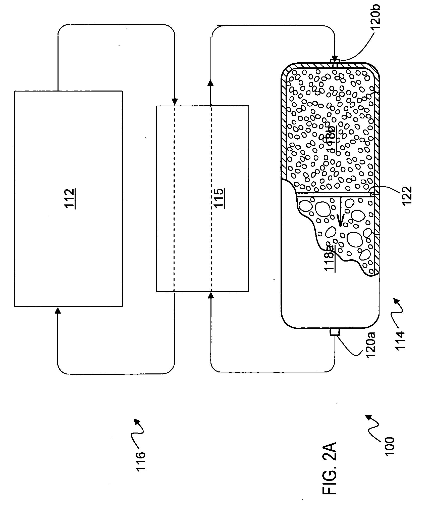
[0062] Referring now to FIG. 2A, there is shown a schematic of a representative fuel cell power system 100 in a first embodiment including an auxiliary tank. System 100 comprises an energy conversion device 112, a reservoir container 114, an auuxuliary tank 115, and a fluid circuit generally denoted by the reference numeral 116. The energy conversion device 112 converts fuel into energy and exhaust, and can be any one of a variety of devices as discussed above with respect to FIG. 1. The reservoir container 114 is partitioned into at least two chambers 118a, 118b, for respectively holding varying quantities of fuel and exhaust. In this regard, the chambers 118a, 118b are adapted to vary inversely in volume such that as fuel is first dispensed from chamber 118a, an amount of exhaust is collected in chamber 118b. After the entire quantity of fuel from chamber 118a has been supplied to the energy conversion device 112 and chamber 118b has filled with exhaust, the reservoir container ca...

second embodiment

[0064] Referring now to FIG. 3, there is shown a schematic of a representative fuel cell power system 30 in a The power system 30 generally includes a reservoir container 32, power stack 34, flow circuit 36 and valve / insulating system (ISS) 38. The reservoir container includes a pair of chambers 40a, 40b of inversely variable volume as described above with respect to the general embodiment illustrated in FIG. 1. As shown in FIG. 3, fluid anode material is initially contained in chamber 40a. The flow circuit 36 contains a pump 42 (a single pump is depicted, but more than one may be installed, with the additional pump(s) located proximal to chamber 40a) to drive the fluid through the system. The fuel is initially dispensed from chamber 40a to the ISS 38. The ISS 38 includes a fuel feed conduit 44 having respective branch lines 46a-d to communicate the anode paste (or reaction products upon reversal of the cycle) from the reservoir container 32 to a plurality of corresponding cell ele...


PUM


Abstract

An energy conversion system is provided including at least one energy conversion device. A reservoir container is provided for storing a quantity of fuel and a quantity of exhaust. The reservoir container includes a container body including at least two chambers of inversely variable volume disposed within said container body for respectively storing a quantity of fuel and receiving a quantity of exhaust, and a structure for decreasing the volume of the first chamber while concurrently increasing the volume of the second chamber. The auxiliary container is in fluid communication with the at least one energy conversion device, the first chamber and the second chamber. The auxiliary container is configured for receiving a quantity of fuel from the first chamber, providing said quantity of fuel to the at least one energy conversion device, receiving a quantity of fuel partially converted from said energy conversion device, and returning a portion of said partially converted fuel to said energy conversion device.

Description

RELATED APPLICATIONS [0001] The present application is a continuation in part of co-pending U.S. patent application Ser. No. 10 / 429,935, filed on May 5, 2003 entitled “Fuel containment and recycling system”, which is a continuation of U.S. patent application Ser. No. 09 / 570,798 filed on May 12, 2000, now U.S. Pat. No. 6,558,825, both of which are incorporated herein by reference.FIELD OF THE INVENTION [0002] The present invention relates generally to fuel and exhaust containment for energy conversion systems, and more particularly, to fuel containers and recycling systems for metal-air fuel cells. BACKGROUND OF THE INVENTION [0003] Fuel cells, and in particular metal-air battery systems, have long been considered a desirable power source in view of their inherent high energy density. A fuel-cell battery includes a cathode, an ionic medium and an anode. A metal-air cell employs an anode comprised of metal particles that is fed into the cell and oxidized as the cell discharges. The ca...

Claims


Application Information

Patent Timeline
IPC IPC(8): H01M8/04H01M4/86H01M6/50H01M8/06H01M8/10H01M8/18H01M8/22H01M10/42H01M12/06H01M50/77
CPCH01M2/40H01M4/02H01M6/5011H01M6/5077H01M8/18H01M8/225H01M10/4214H01M12/06H01M2300/0014Y02E60/50Y02E60/10H01M50/77
Inventor FARIS, SADEG M.
Owner FARIS SADEG M
Why Eureka
Try Eureka