Cell

a cell and cell technology, applied in the field of cells, can solve the problems of short circuit between the negative and positive electrode terminals of the cell, decrease the thickness of the cpp layer, etc., and achieve the effect of improving the cell capacity and superior performan

Active Publication Date: 2006-06-15
MURATA MFG CO LTD
View PDF6 Cites 35 Cited by
  • Summary
  • Abstract
  • Description
  • Claims
  • Application Information

AI Technical Summary

Benefits of technology

[0021] According to the embodiments of the present invention, problems can be solved which may arise when a thin laminate film is used as an exterior packaging material in order to improve the cell capacity, and a cell having superior performance can be obtained in which no short-circuiting occurs, nor does moisture infiltration.

Problems solved by technology

However, besides the above problem, other problems may arise when the thickness of the CPP layer is decreased.
For example, as shown in FIG. 5, short-circuiting may disadvantageously occur between the electrode terminal 2 and the Al layer when cutting burrs (hereinafter referred to as “burrs” in some cases) 30, which are generated when the laminate film 10 is cut, penetrate the CPP layer, resulting in short-circuiting between the negative and positive electrode terminals of the cell.

Method used


Image

  • Cell
  • Cell
  • Cell

Examples


example 1

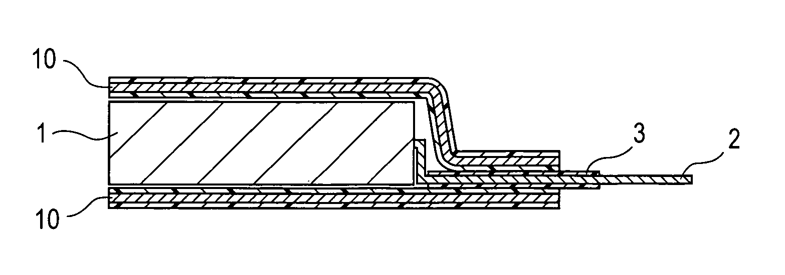
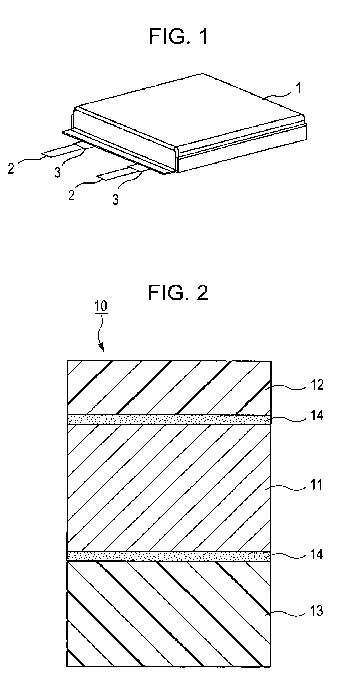
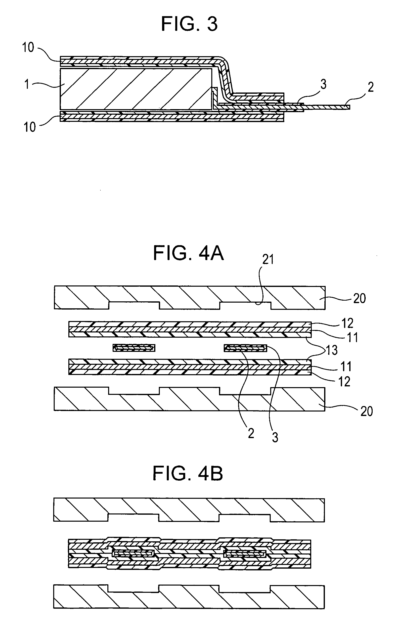
[0096] Cells of Examples 1-1 to 1-3 and Comparative Examples 1-1 to 1-7 were formed by changing the width of the heater head, and in addition, the temperature of the heater head and the pressure in thermal welding were also changed, so that the thickness t1 of the thermal welded portion and the thickness t2 of the edge portion of the laminate film were changed. The cells of Examples 1-1 to 1-3 and Comparative Examples 1-1 and 1-2 were formed by using a heater head having a width of 2.0 mm, the cells of Comparative Examples 1-3 to 1-7 were formed using a heater head having a width of 3.0 mm, and for exterior packaging of each cell, an aluminum laminate film having a thickness of 85 μm was used, the film being composed of a nylon layer 15 μm thick, an adhesive layer 3 μm thick, an aluminum layer 35 μm thick, an adhesive layer 2 μm thick, and a CPP layer 30 μm thick in that order from the outer side. In addition, as the electrode terminal, an aluminum ribbon 4 mm wide and 70 μm thick w...

example 2

[0110] By changing the structure of the laminate film used as an exterior packaging material for the cell element and the temperature and pressure of the heater head in thermal welding, the thickness t3 of the thermal welded portion and the thickness t4 of the electrode terminal portion were changed, so that various test cells were formed. As the laminate film used as an exterior packaging material, one of the following laminate films was used. That is, there was used an aluminum laminate film having a total thickness of 85 μm composed of a 15 μm-thick outermost nylon layer, 3 μm-thick adhesive layer, 35 μm-thick aluminum foil, 2 μm-thick adhesive layer, and 30 μm-thick CPP layer or an aluminum laminate film having a total thickness of 75 μm, which had the same structure as that described above except that the thickness of the CPP layer was 20 μm (15 μm-thick nylon layer, 3 μm-thick adhesive layer, 35 μm-thick aluminum foil, 2 μm-thick adhesive layer, and 20 μm-thick CPP layer). In ...


PUM

PropertyMeasurementUnit
thicknessaaaaaaaaaa
thicknessaaaaaaaaaa
thicknessaaaaaaaaaa

Abstract

A highly safety cell is provided in which short-circuiting is unlikely to occur. In order to prevent short-circuiting, for example, burrs generated when a laminate film used as an exterior packaging material is cut are prevented from penetrating an interior resin layer of the laminate film. When an electrode terminal extension side of the laminate film is thermal welded, heating and compression are performed by a heater head on a part of the laminate film apart from the edge portion thereof so that the thickness of the above edge portion is larger than that of a thermal welded portion. In addition, thermal welding is performed so that the thickness of a thermal welded portion including an electrode terminal is larger than that of a thermal welded portion including no electrode terminal, and as a result, short-circuiting can be more effectively prevented.

Description

CROSS REFERENCES TO RELATED APPLICATIONS [0001] The present invention contains subject matter related to Japanese Patent Application JP 2004-357820 filed in the Japanese Patent Office on Dec. 10, 2004, the entire contents of which are incorporated herein by reference. BACKGROUND OF THE INVENTION [0002] 1. Field of the Invention [0003] The present invention relates to cells, and more particularly, relates to a cell formed by using a laminate film as an exterior packaging material. [0004] 2. Description of the Related Art [0005] In recent years, a great number of portable electronic apparatuses such as camera-incorporated VTRs (videotape recorders), mobile phones, and laptop computers have been introduced into the market, and trends toward miniaturization of the portable electronic apparatuses and reduction in weight thereof have been positively pursued. Concomitant with the trends described above, cells used as power sources of portable electronic apparatuses are rapidly increasing i...

Claims


Application Information

Patent Timeline
Patent Type & Authority Applications(United States)
IPC IPC(8): H01M2/08H01M2/02H01M10/40H01M2/06H01M50/126H01M50/133H01M50/141H01M50/178H01M50/417H01M50/55H01M50/553H01M50/562H01M50/566
CPCH01M2/021H01M6/166H01M4/13H01M10/0431H01M10/052H01M10/0525H01M10/0565H01M10/0587Y02E60/122H01M6/181H01M2300/0082H01M6/164H01M6/02H01M4/661H01M4/625H01M4/623H01M4/133H01M4/131H01M4/06H01M2/1653H01M2/162H01M2/08H01M2300/0037H01M2220/30H01M10/0569H01M10/0568H01M2/06B29L2031/3468B29C65/18B29C66/1122B29C66/32B29C66/433B29C66/72321B29C66/7352B29C66/81431B29C66/83221B29K2705/02B29C65/08B29C66/71Y02E60/10H01M50/44Y02P70/50H01M50/553H01M50/178H01M50/55H01M50/417H01M50/562H01M50/126H01M50/141H01M50/133H01M50/566B29C66/549B29C66/53461B29C66/112B29C66/131B29K2077/00B29K2067/003B29K2023/12H01M50/10H01M50/20H01M50/183H01M50/124H01M50/46B32B7/12B32B15/08B32B15/20B32B27/32B32B27/36B32B2274/00B32B2323/10B32B2367/00B32B2457/10B32B2553/00B29C65/02B29C66/41B29K2623/12B29K2655/00B29L2031/7146B32B5/142B32B15/085B32B15/088B32B15/09B32B27/34B32B2250/03B32B2255/06
Inventor HATTA, KAZUHITOSHIBUYA, MASHIO
Owner MURATA MFG CO LTD
Why Eureka
Try Eureka