System and method for identifying and controlling ophthalmic surgical devices and components

Active Publication Date: 2006-06-15
ALCON INC
View PDF15 Cites 202 Cited by
  • Summary
  • Abstract
  • Description
  • Claims
  • Application Information

AI Technical Summary

Benefits of technology

[0016] System embodiments can be configured to enable or disable a surgical device. If the data received from the identifier satisfies the criteria, then the device can be enabled. The device can also be conditionally enabled based on, for example, whether the component has been used before, or based on an amount of time that has passed since a first or prior use of the component. A certain number of repeat uses of a component may be allowed, but the device can be disabled after a certain number of uses or after a certain amount of time. Other safety precautions can also be implemented, such as generating a message to a surgeon that the component has been previously used. Further, data can be written back to the component identifier for future reference. The data may include a date of usage, a number of uses of the component, a duration of use of the component, or a power setting of the component. The devic

Problems solved by technology

For example, components may be discarded because they are contaminated or because they have exceeded a certain useful life.
Thus, the selection of components and operation of the device are often subject to user discretion.
Known systems and techniques for matching surgical devices and components, however, can be prone to error and require additional time and effort to ensure that the correct component is attached to the correct surgical device.
Further, there are problems associated with third parties manufacturing components for replacement of original surgical components.
For example, they may be lower quality components compared to components from original manufacturers.
They may also not function as intended and be less reliable than original manufacturer components, thus causing system operation and safety concerns.
Additionally, manufacturers of original equipment experience

Method used


Image

  • System and method for identifying and controlling ophthalmic surgical devices and components
  • System and method for identifying and controlling ophthalmic surgical devices and components
  • System and method for identifying and controlling ophthalmic surgical devices and components

Examples


Embodiment Construction

[0030] In the following description, reference is made to the accompanying drawings, which form a part hereof, and which show by way of illustration specific embodiments. It is to be understood that structural changes may be made without departing from the scope of the embodiments.

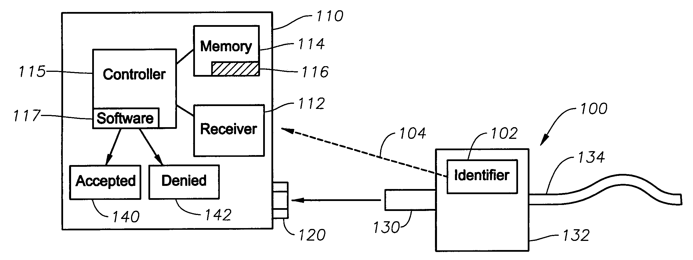
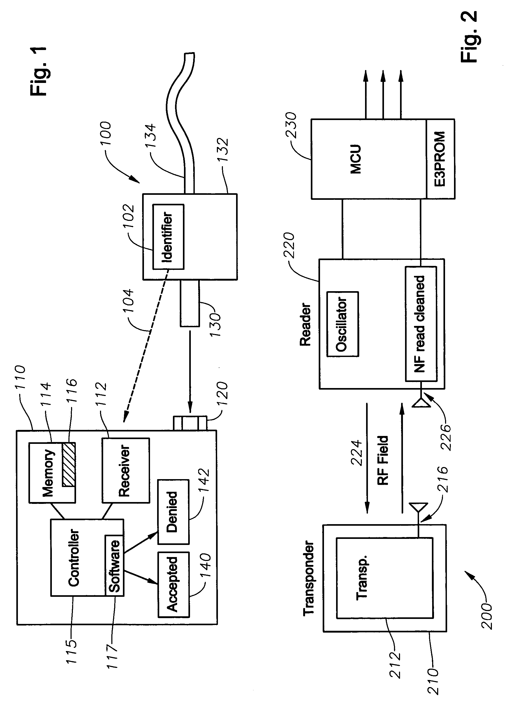
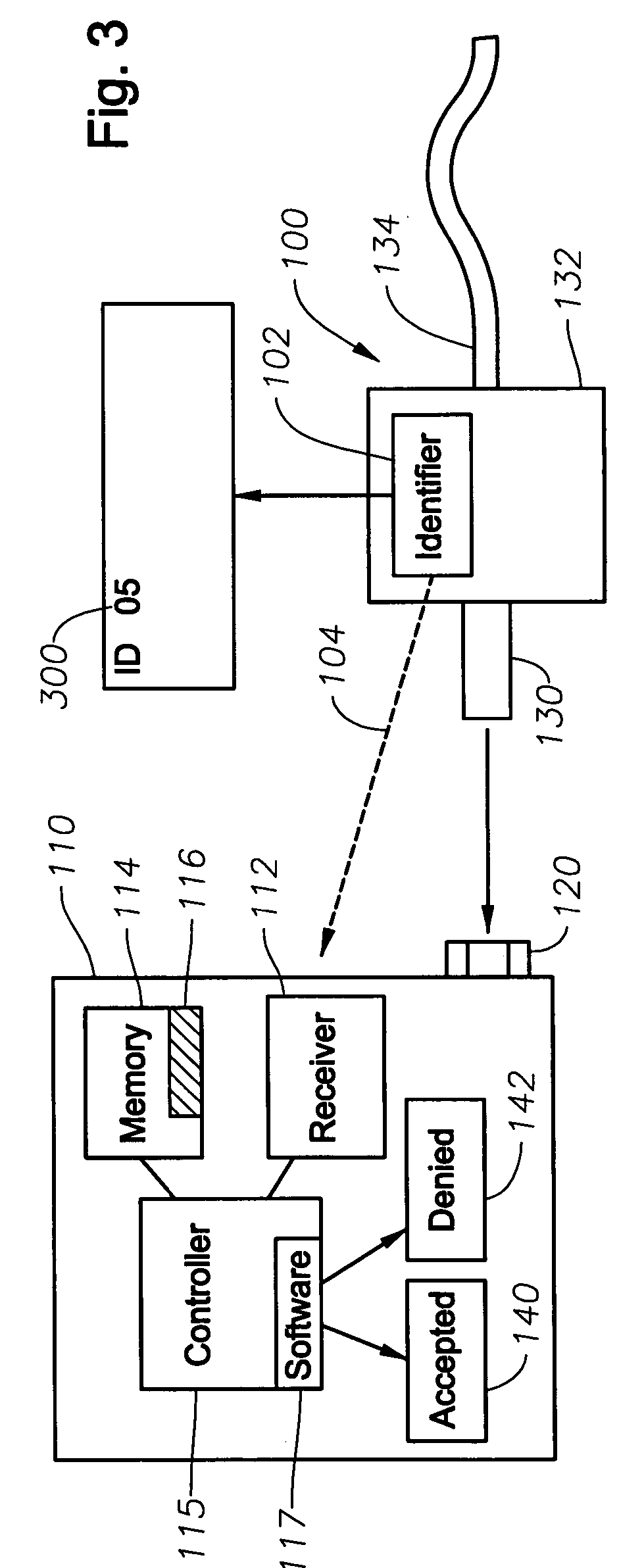
[0031] System and method embodiments provide for electronic identifiers to be integrated into ophthalmic surgical equipment. The electronic identifiers can perform various functions, including identifying a component or adaptation that can be used with an ophthalmic surgical device, selectively enabling and disabling equipment that is used with components, identifying unauthorized components, such as components that are not compatible with a device and components from third party manufacturers, providing calibration data, and providing for read / write applications between an ophthalmic surgical device and a component used with the device. Thus, embodiments allow for more accurate determinations whether cer...


PUM


Abstract

System and method for identifying a component, such as an optical probe or pneumatic scissors, of an ophthalmic surgical device. A component of a surgical device includes an identifier, such as a RFID tag. Data from the RFID tag is transmitted to a RFID reader in the device. A controller determines whether the component corresponding to the received data is operable with the surgical device based on criteria, such as whether the received data is an authorized code that matches data stored in memory or whether the received data solves or satisfies an algorithm. The authorized codes are selected from a larger set of available codes. The controller enables or disables the operation of the device with the component based on whether the criteria is satisfied, the number of uses of the component, an amount of time that has passed since the component has been used, or a geographic location. The RFID data can also be used to calibrate the surgical device for use with the particular component and for inventory and monitoring purposes.

Description

TECHNICAL FIELD OF THE INVENTION [0001] The present invention relates to ophthalmic surgical devices, and, more particularly, to the use of electronic identifiers on components of ophthalmic surgical devices that can be used to transmit and receive data related to the components and use thereof with the ophthalmic surgical device. BACKGROUND OF THE INVENTION [0002] Various surgical devices operate using components that are discarded or replaced for various reasons. For example, components may be discarded because they are contaminated or because they have exceeded a certain useful life. Thus, unlike permanent surgical equipment, some components are used one time, or a limited number of times, and then must be replaced for safety and / or other considerations. Determinations regarding whether a particular component is suited for a particular surgical device are typically made by a technician or surgeon, for example, based on whether the component fits within or attaches to the surgical...

Claims


Application Information

Patent Timeline
IPC IPC(8): A61B17/00A61B34/10
CPCA61B19/44A61B2017/00482A61B2019/448A61B2019/4826A61B2019/4873G06Q10/087A61F9/008A61F2009/00874G06K17/00G06K2017/0064G06K2017/009A61F9/007G06K19/07A61B2090/0805A61B90/90A61B90/98A61B2090/0814A61B17/00
Inventor TODD, KIRK W.EKVALL, JOHAN G.REED, FREDERICK M.ROWE, T. SCOTTHORVATH, CHRISTOPHER
Owner ALCON INC
Why Eureka
Try Eureka