

Medical devices formed with a sacrificial structure and processes of forming the same
a technology of sacrificial structure and medical devices, applied in the field of medical devices, can solve the problems of increasing the susceptibility to pin hole formation and rupture, reducing the flexibility of balloons, etc., and achieve the effect of reducing the overall profile of the devi
- Summary
- Abstract
- Description
- Claims
- Application Information
AI Technical Summary
Benefits of technology
Problems solved by technology
Method used
Image

Examples
Embodiment Construction
[0036] While this invention may be embodied in many different forms, there are described in detail herein specific embodiments of the invention. This description is an exemplification of the principles of the invention and is not intended to limit the invention to the particular embodiments illustrated.
[0037] All published documents, including all US patent documents, mentioned anywhere in this application are hereby expressly incorporated herein by reference in their entirety. Any copending patent applications, mentioned anywhere in this application are also hereby expressly incorporated herein by reference in their entirety.
[0038] Some embodiments of the present invention are directed to processes for forming medical devices, especially those deployed and operated through various body lumens including, for example, vascular channels, and to devices obtained from such processes.
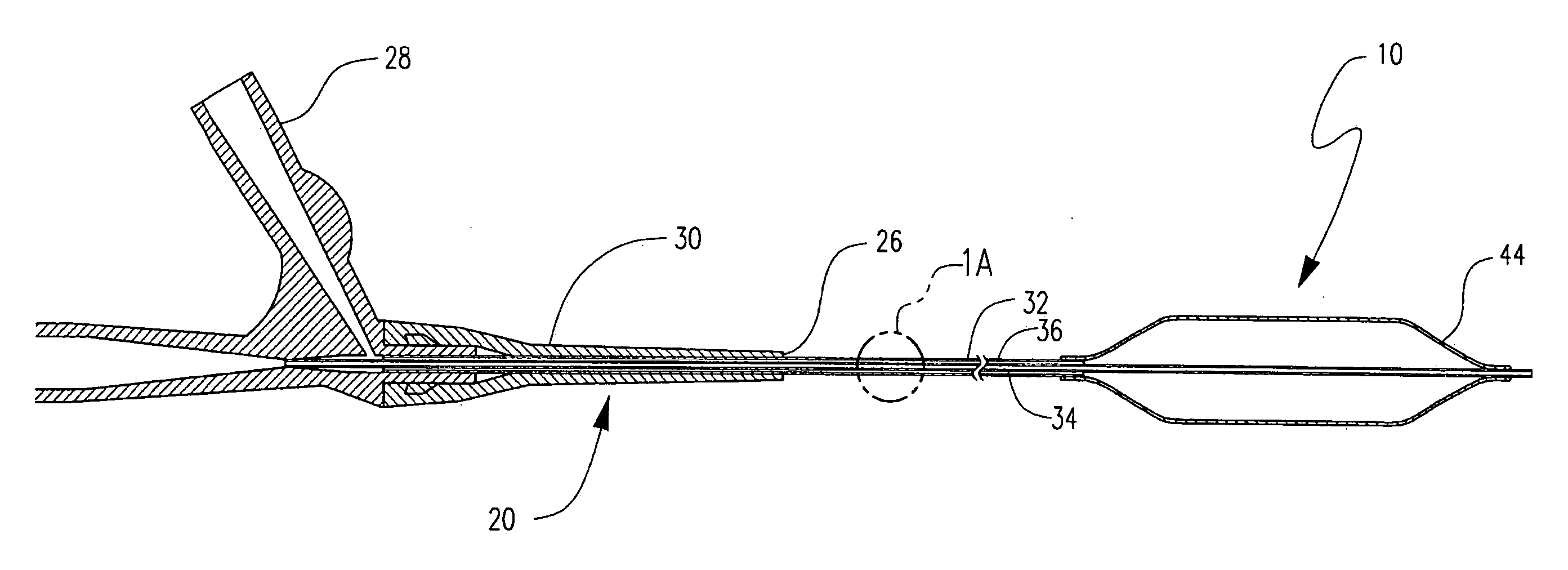
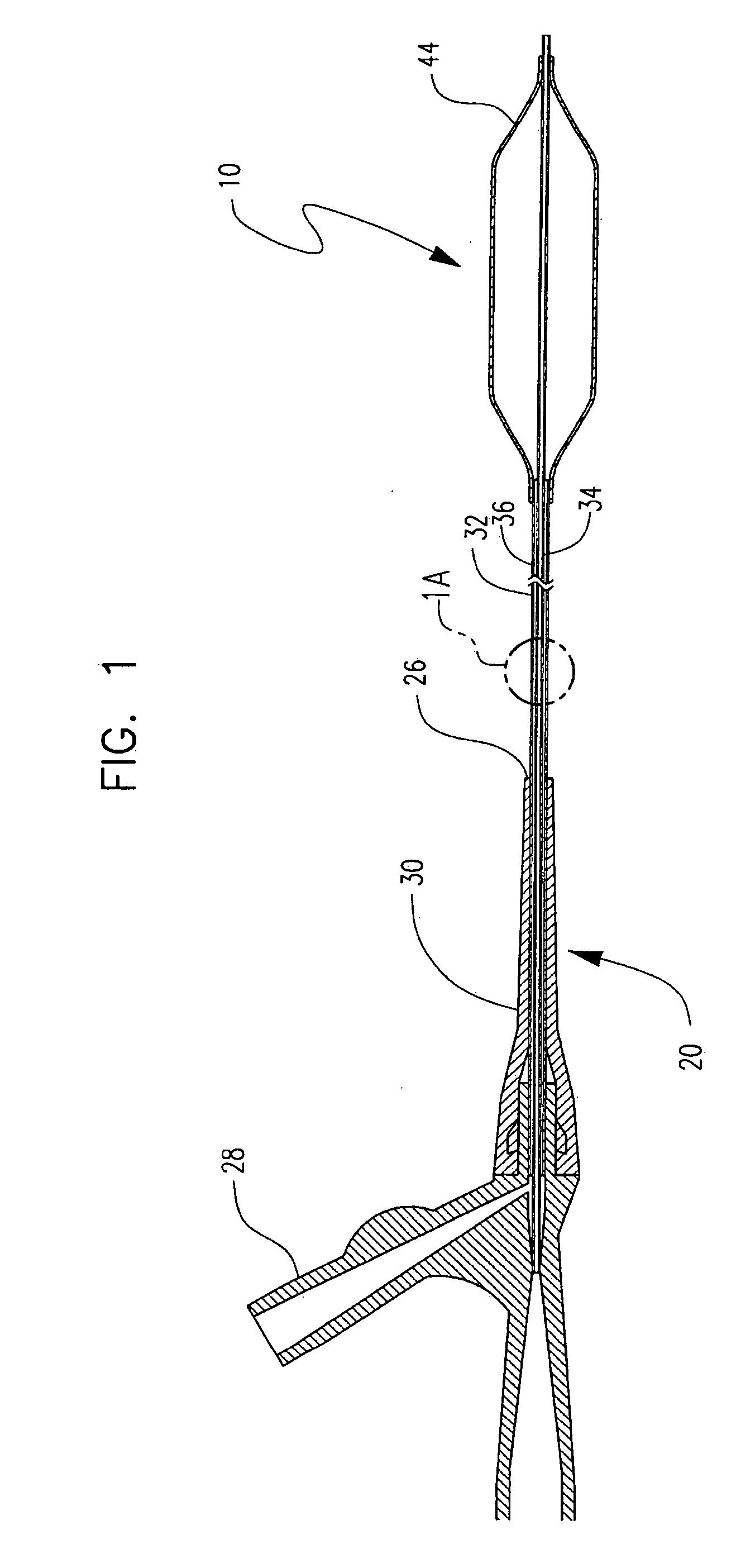
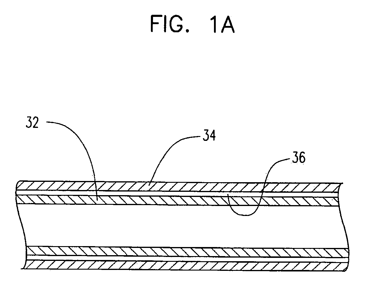
[0039] Referring now to the figures, FIG. 1 shows balloon 10 in combination with a catheter assembly 2...
PUM
| Property | Measurement | Unit |
|---|---|---|
| temperature | aaaaa | aaaaa |
| melting temperature | aaaaa | aaaaa |
| temperatures | aaaaa | aaaaa |
Abstract
Description
Claims
Application Information