This helps you quickly interpret patents by identifying the three key elements:
Problems solved by technology
Method used
Benefits of technology
Benefits of technology
[0011] A first object of the present invention to effectively reduce the size of a video memory, such as a frame memory or the like, while performing a decoding process for obtaining played-back video data from encoded video data without a conventional scalable decoder and zero-padding circuit.
[0024] Therefore, the compressed video data obtained by the compression circuit is stored in the video memory while ordinary played-back video data is obtained by the encoded video decoding circuit. As a result, the encoded video decoding circuit has the ordinary structure, which does not include the conventional zero-padding circuit, and does not change the process of decoding encoded video data, and a compression circuit and a decompression circuit are only added, so that the amount of data stored in the video memory can be reduced, and therefore, the size of the video memory can be reduced, while suppressing a degradation in image quality.
[0025] Particularly, in the present invention, the video memory stores not only played-back video data currently obtained by the encoded video decoding circuit, but also a large amount of compressed video data previously obtained. The large amount of compressed video data stored in the video memory is used as a basis for video display on a video display device. Therefore, it is not necessary that a video display process be delayed until all pixel data corresponding to at least one line are accumulated, depending on the timing of decoding encoded video data as in conventional technologies. In addition, a display memory specialized for video display does not have to be provided in addition to the video memory.
Problems solved by technology
Thus, in the above-described two conventional technologies, although the size of the accumulation memory can be effectively reduced, a portion of the existing video playback device needs to be altered, i.e., the existing video playback device cannot be used without alteration.
Method used
Image
Click on the blue label to locate the original text in one second.
Reading with bidirectional positioning of images and text.
Examples
example 1
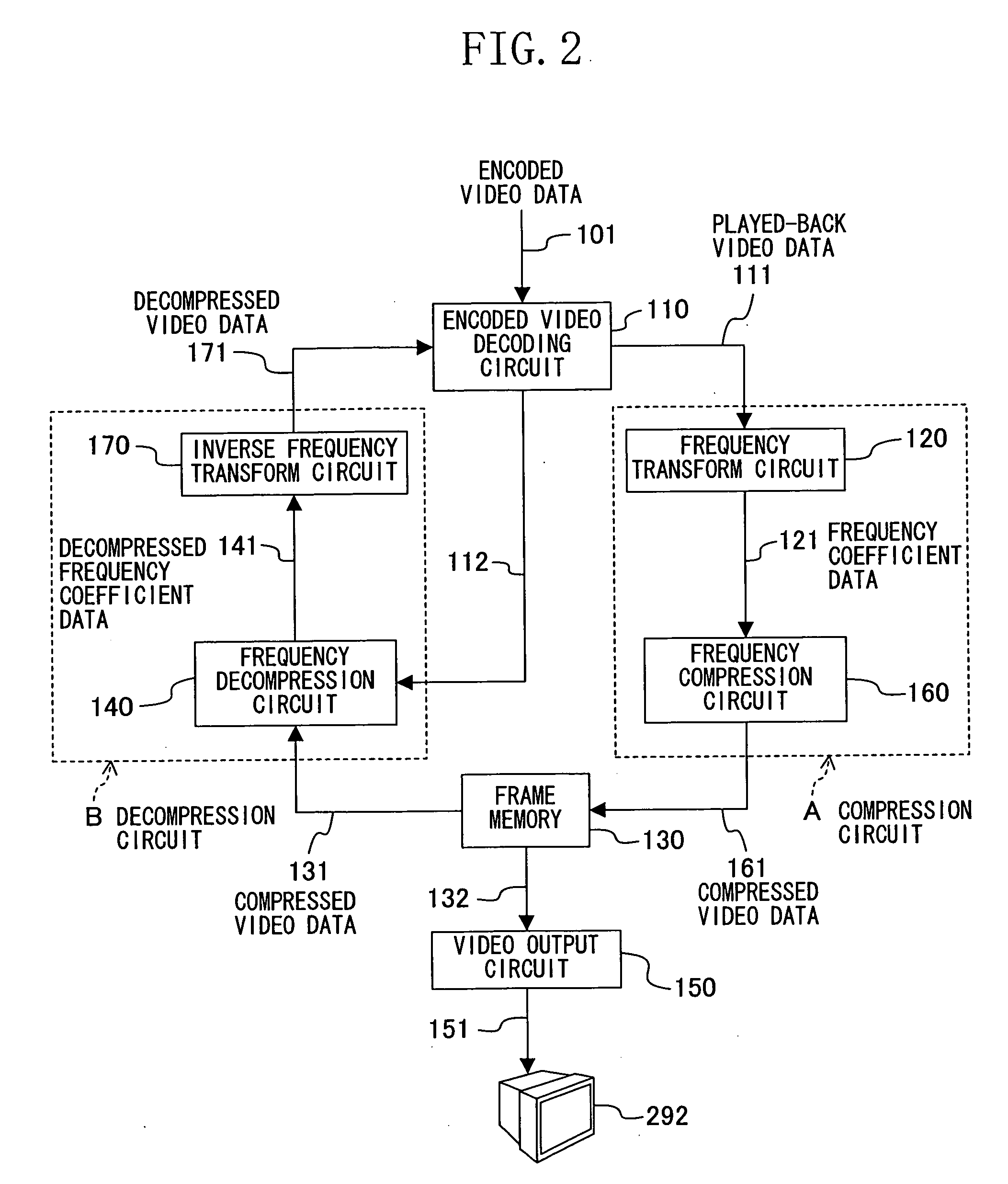
[0036]FIGS. 1 and 2 illustrate a whole structure of a video playback device according to Example 1 of the present invention.
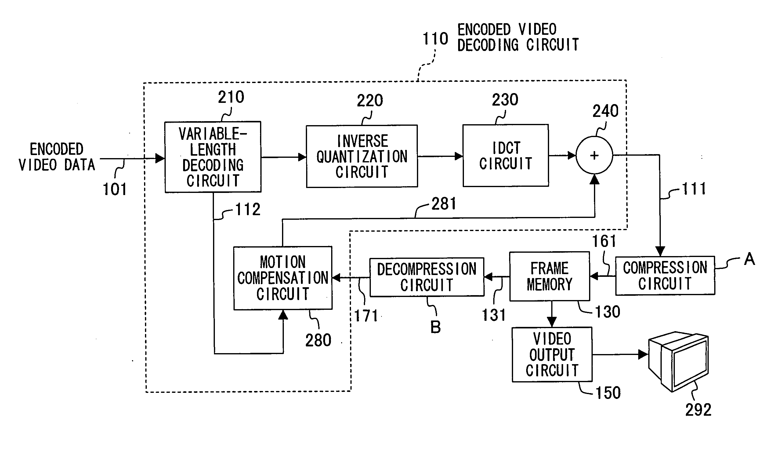
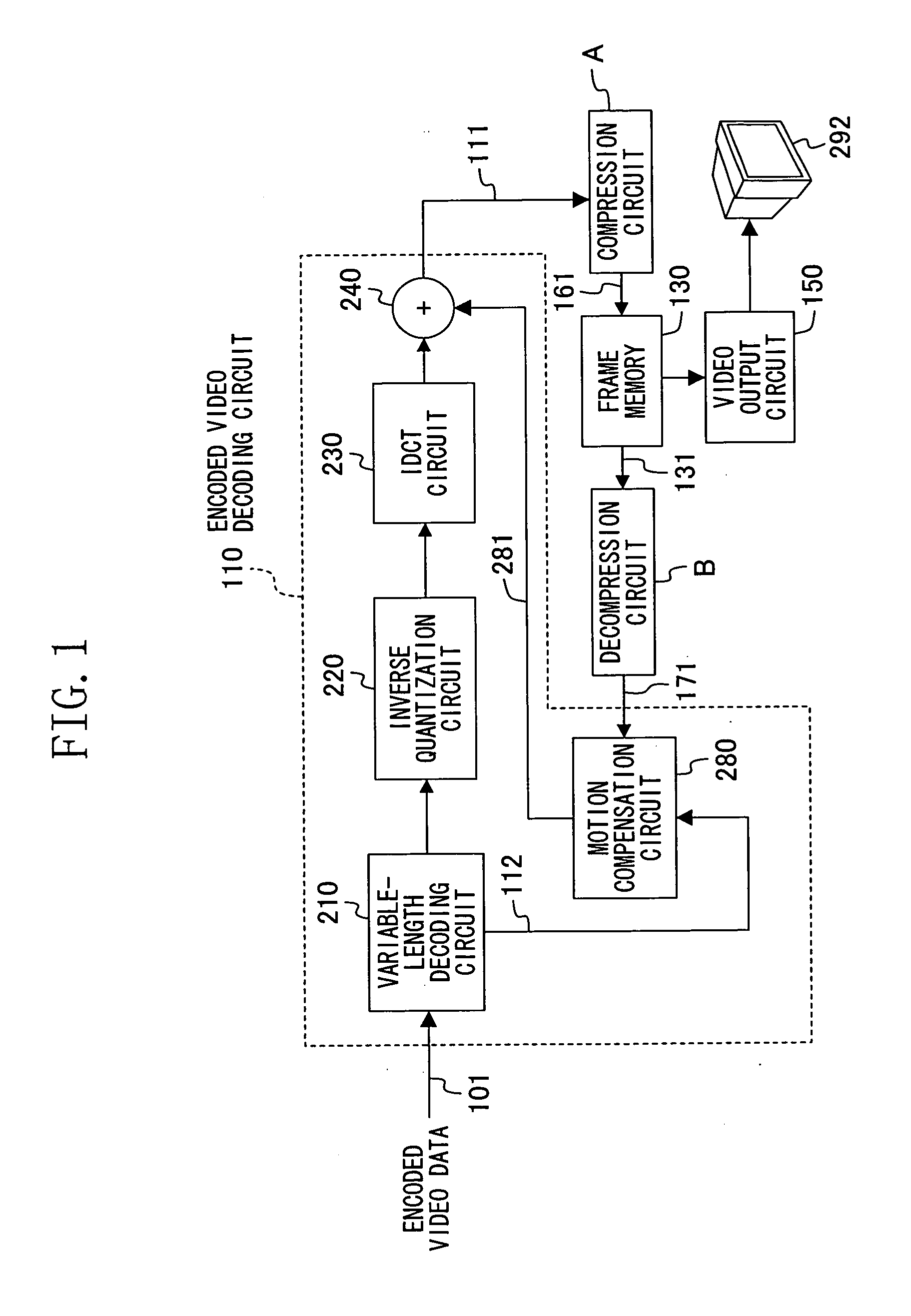
[0037] Referring to FIGS. 1 and 2, reference numeral 110 indicates an encoded video decoding circuit, and reference numeral 130 indicates a frame memory (video memory) whose size is reduced according to the present invention. The encoded video decoding circuit 110 receives encoded video data 101 and decodes the encoded video data 101 to obtain resultant decoded video data (differential pixel data), and combines the decoded video data with predetermined reference video data to generate played-back video data 111.
[0038] As illustrated in FIG. 1, the encoded video decoding circuit 110 comprises a variable-length decoding circuit 210, an inverse quantization circuit 220, an IDCT circuit 230, an adder 240, and a motion compensation section 280. Specifically, the encoded video decoding circuit 110 has an ordinary structure in which the zero-padding circuit 225 is r...
example 2
[0056] Next, a video playback device according to Example 2 of the present invention will be described. Note that the whole structure of the video playback device of Example 2 is similar to that of FIGS. 1 and 2 and is not shown. The video playback device of Example 2 is different from that of Example 1 in the frequency compression circuit 160 and the frequency decompression circuit 140, which are involved in data compression and decompression.
[0057] In Example 2, the frequency compression circuit 160 compresses the frequency coefficient data 121, which is an object to be compressed, based on frequency compression characteristics of the data illustrated in FIG. 5, and stores the resultant compressed frequency coefficient data into the frame memory 130. In the frequency decompression circuit 140, the compressed video data 131 read from the frame memory 130 is decompressed based on characteristics which are inverse to the compression characteristics of FIG. 5.
[0058] Hereinafter, Exa...
example 3
[0060] Next, a video playback device according to Example 3 of the present invention will be described.
[0061]FIG. 6 illustrates a structure of the video playback device of Example 3 of the present invention. The video playback device of FIG. 6 is different from the video playback device (FIG. 2) of Example 1 in that a compression characteristics control circuit 480 is added.
[0062] The compression characteristics control circuit 480 changes compression characteristics, depending on characteristics of video to be compressed. The compression characteristics control circuit 480 determines compression characteristics based on the frequency coefficient data 121 from the frequency transform circuit 120, and outputs compression characteristics control signals 481 and 482, which are based on the determined compression characteristics, to the frequency compression circuit 160 and the frequency decompression circuit 140, respectively.
[0063] The compression characteristics control circuit 48...
PUM
Abstract
A video playback device of decoding encoded video data is additionally provided with a compression circuit and a decompression circuit in an existing encoded video decoding circuit. In the compression circuit, a frequency transform circuit transforms played-back video data obtained from the encoded video decoding circuit into frequency coefficient data, which is in turn subjected to IDCT having a reduced order in a frequency compression circuit to obtain compressed video data. The compressed video data, which is image space data having a reduced image size, is stored in a frame memory. The decompression circuit comprises a frequency decompression circuit and an inverse frequency transform circuit which performs a process inverse to that of the compression circuit. The compressed video data from the frame memory is converted by a video output circuit into data which can be displayed, and the resultant data is output to a video display device. Therefore, the additional components are provided while the existing device is used as it is, thereby reducing the size of a frame memory.
Description
CROSS REFERENCE TO RELATED APPLICATIONS [0001] This Non-provisional application claims priority under 35 U.S.C. §119(a) on Patent Application No. 2004-357661 filed in Japan on Dec. 10, 2004, the entire contents of which are hereby incorporated by reference. BACKGROUND OF THE INVENTION [0002] The present invention relates to a video playback device of playing back video, such as a moving picture or the like, from encoded video data. More particularly, the present invention relates to a technology of reducing the size of a frame memory for storing decoded data when video data encoded with MPEG or the like is decoded and played back. [0003] Conventionally, a technology of reducing the size of a frame memory in a process of decoding encoded moving picture data is described in TECHNICAL REPORT OF IEICE, DSP94-108 (Publication 1). This technology employs a scalable decoder. The scalable decoder is a technology of performing decoding using a portion of encoded moving picture data. Specific...
Claims
Application Information
Patent Timeline
Application Date:The date an application was filed.
Publication Date:The date a patent or application was officially published.
First Publication Date:The earliest publication date of a patent with the same application number.
Issue Date:Publication date of the patent grant document.
PCT Entry Date:The Entry date of PCT National Phase.
Estimated Expiry Date:The statutory expiry date of a patent right according to the Patent Law, and it is the longest term of protection that the patent right can achieve without the termination of the patent right due to other reasons(Term extension factor has been taken into account ).
Invalid Date:Actual expiry date is based on effective date or publication date of legal transaction data of invalid patent.

