Sound-absorbing structure body
a structure body and sound absorption technology, applied in the field of sound absorption structure bodies, can solve the problems of difficulty in providing two or more peak frequencies, and achieve the effect of increasing the sound absorption coefficient near the peak frequency of sound absorption
- Summary
- Abstract
- Description
- Claims
- Application Information
AI Technical Summary
Benefits of technology
Problems solved by technology
Method used
Image
Examples
first embodiment
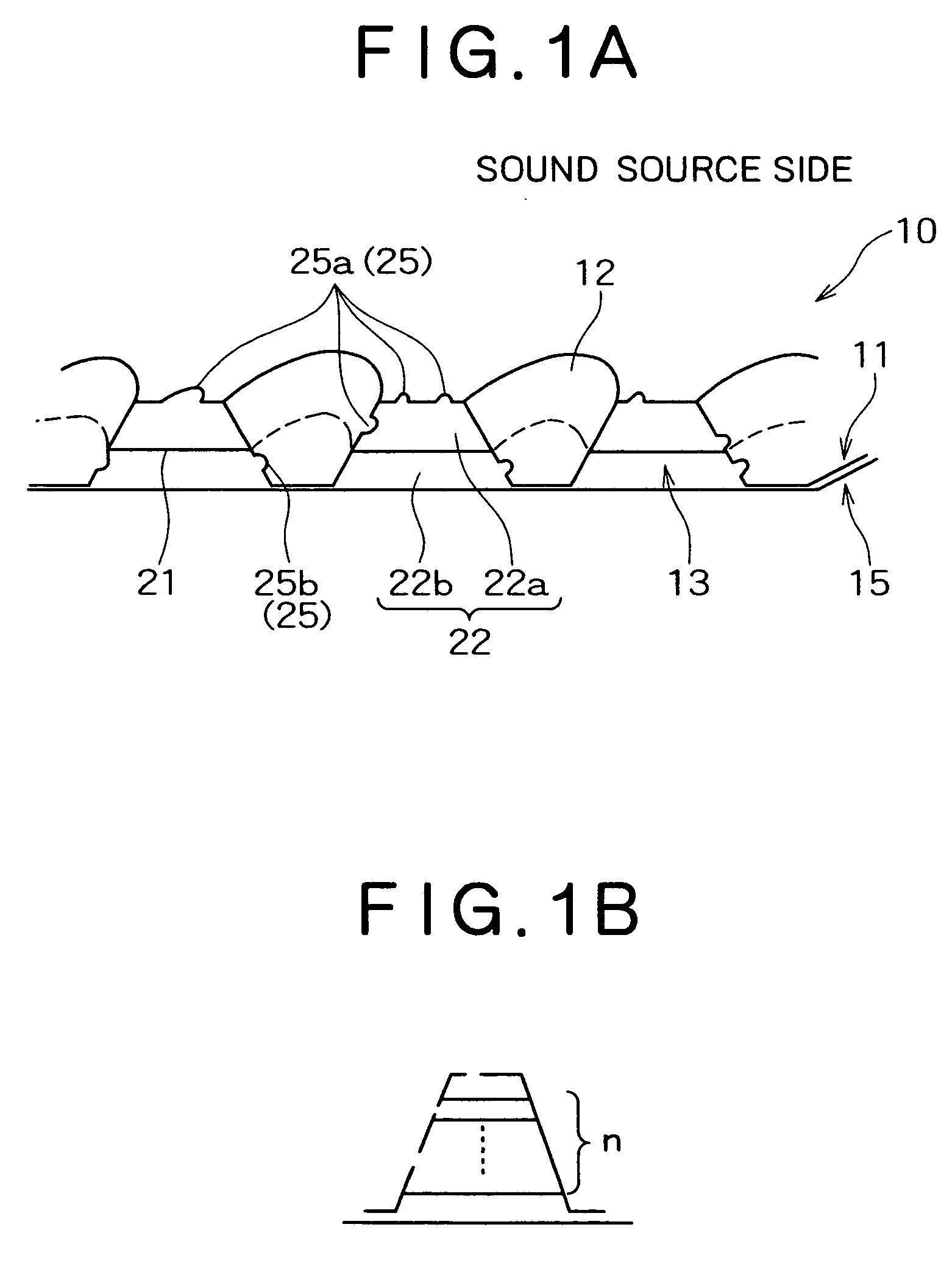
[0030] FIGS. 1(a) and 1(b) are explanatory diagrams each showing a schematic configuration of a sound-absorbing structure body according to a first embodiment of the present invention.
[0031] In FIG. 1(a), a sound-absorbing structure body 10 is basically constituted by a laminated structure body comprising a ridge-groove board 11 formed with a large number of independent grooves 12 and a closing board 15 which is joined to the ridge-groove board 11 so as to form a hollow portion 13 between adjacent grooves (anti-sound source side of the ridges).
[0032] In the laminated structure body are provided a partition board 21 for partitioning the hollow portion 13 into two or more partitioned spaces 22 and hole groups 25 which are opened in the ridge-groove board 11 so as to communicate with each of the two or more partitioned spaces 22.
[0033] The ridge-groove board 11 comprises a large number of cone (truncated cone)-shaped grooves 12. The grooves 12 may be not only in such a truncated con...
second embodiment
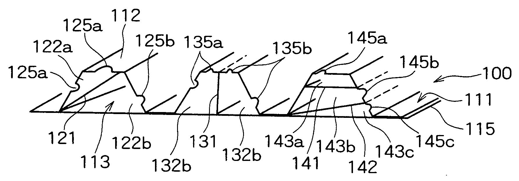
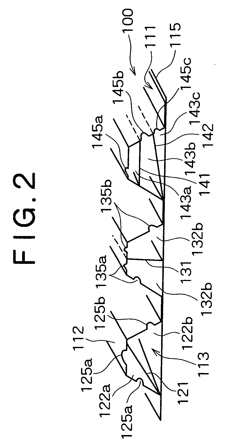
[0041] Next, a sound-absorbing structure 100 according to a second embodiment of the present invention will be described below with reference to FIG. 2.
[0042] The sound-absorbing structure body 100 is basically constituted by a laminated structure body comprising a ridge-groove board 111 having alternate ridges 112 and grooves and a closing board 115 joined to the bottoms of the grooves so as to form a hollow portion 113 within each of the ridges 112. In this laminated structure body there are provided partition boards 121, 131, 141, 142 each for partitioning each hollow portion 113 into two or more partitioned spaces and two or more hole groups 125a, 125b, 135a, 135b, 145a, 145b, 145c which are opened to the surface of the ridge-groove board 111 so as to communicate with two or more partitioned spaces 122a, 122b, 132a, 132b, 143a, 143b, 143c.
[0043] In the left ridge 112 shown in FIG. 2, a partition board 121 is disposed obliquely in a diagonal form to partition the hollow portion...
third embodiment
[0047] Next, a sound-absorbing structure body 200 according to a third embodiment of the present invention will be described below.
[0048] In the sound-absorbing structure body 200, foils 201a and 201b are added into the partitioned space 22a used in the sound-absorbing structure of the first embodiment. As shown in the left-hand hollow portion in FIG. 3, a first perforated foil 201a is fitted into the first partitioned space in parallel with the closing board 15, making it possible for the first foil 201a to vibrate or be rubbed with air passing into and out of the first hole group 25a. Into the second partitioned space is fitted a second perforated foil 201b in parallel with the closing board 15, making it possible for the second foil 201b to vibrate or be rubbed with air passing into and out of the second hole group 25b.
[0049] As each of the foils 201a and 201b, there may be used a mere foil, foil formed in a ridge-groove shape, foil formed in a folded shape, or foil having plur...
PUM
 Abstract
Description
Claims
Application Information
 - R&D
- Intellectual Property
- Life Sciences
- Materials
- Tech Scout
- Unparalleled Data Quality
- Higher Quality Content
- 60% Fewer Hallucinations
Browse by: Latest US Patents, China's latest patents, Technical Efficacy Thesaurus, Application Domain, Technology Topic, Popular Technical Reports.
© 2025 PatSnap. All rights reserved.Legal|Privacy policy|Modern Slavery Act Transparency Statement|Sitemap|About US| Contact US: help@patsnap.com


