Ultraviolet emitter display

a technology of emitter display and ultraviolet light, which is applied in the direction of discharge tube luminescnet display, identification means, instruments, etc., can solve the problems of significant fabrication drawbacks or at the very least performance or cost limitations, pdps have relatively limited lifetimes and are extremely costly to produce, and crts are relatively heavy, bulky, and limited in siz

Inactive Publication Date: 2006-06-22
HEWLETT PACKARD DEV CO LP
View PDF9 Cites 54 Cited by
  • Summary
  • Abstract
  • Description
  • Claims
  • Application Information

AI Technical Summary

Problems solved by technology

Each of these devices has certain benefits combined with, in many cases, significant drawbacks in fabrication, or at the very least performance or cost limitations.
PDPs have relatively limited lifetimes and are extremely costly to produce.
CRTs are relatively heavy, bulky, and are limited in size.
OLEDs have relatively limited lifetimes, and are particularly susceptible to blue degradation.
Large LCD panels are relatively costly to produce.
LCDs require expensive substrates to manufacture successfully, as well as expensive polarizers, both contributing to their high cost.
PDPs require high voltage drivers, expensive components required for viewing, as well as relatively expensive substrates.
Although OLEDs can be fabricated in a relatively inexpensive roll-to-roll process, the lifetimes of such devices circa 2004 are relatively limited.
Further, the ability for the display to demonstrate a long lifetime is highly desirable, as replacement of the display after only a few years of use is a significant drawback.

Method used


Image

  • Ultraviolet emitter display
  • Ultraviolet emitter display
  • Ultraviolet emitter display

Examples


Embodiment Construction

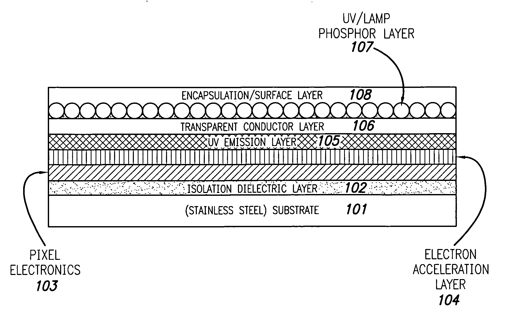
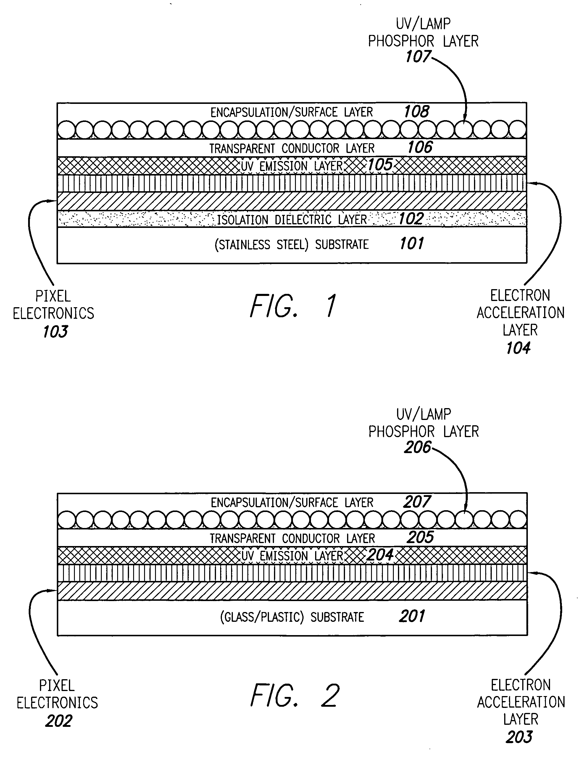
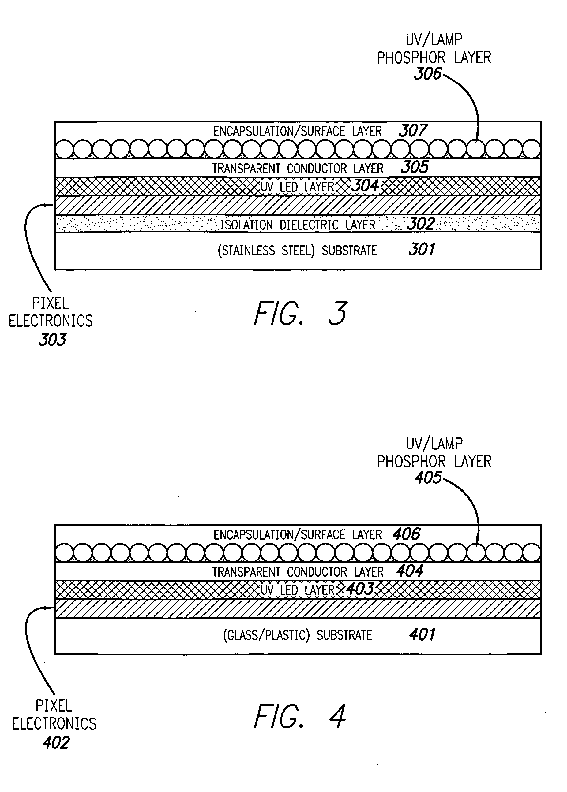
[0022] The present design is a relatively lightweight, thin, color display fabricated from UV light emitters. The emission layer can be either an array of ultraviolet (UV) LEDs or a material that when excited by ballistic electrons, having electron energy levels in the range of approximately 5 to 20 eV, emits UV light.

[0023] Operation of UV LEDs are as follows. UV LED emitters are available from various vendors, including Nichia Corporation of Tokushima, Japan. In general, UV LEDs convert UV light into red, green, and blue light using RGB phosphors, or white phosphors and appropriate color filters. Phosphors may be exposed to some form of excitation, such as electrons, photons, current, and so forth. The phosphors so exposed reemit absorbed energy in the form of light, usually in the longer wavelength region, an effect known as luminescence.

[0024] Because LEDs are monochromatic by nature, phosphors may be used in so-called white LEDs to achieve white light in a simple and efficien...


PUM


Abstract

An ultraviolet emitter display apparatus and method for making the display is disclosed. The device includes a substrate layer, a pixel electronics layer positioned above the substrate layer, the pixel electronics layer including electronics to drive the ultraviolet emission display. Ultraviolet (UV) emitters may be located above the pixel electronics layer, where the UV emitters may comprise a layer of UV light emitting diodes (LEDs) or a combination of an electron acceleration layer and a UV emission layer. The design further includes a phosphor layer comprising a plurality of phosphor elements, either white phosphor elements in combination with color filters or color phosphor elements.

Description

BACKGROUND OF THE INVENTION [0001] 1. Field of the Invention [0002] The present invention relates generally to the field of display devices, and more particularly to screens and related hardware employed in color display devices. [0003] 2. Description of the Related Art [0004] Currently available color display devices are fabricated using various materials in several different arrangements. State of the art emissive display devices include plasma displays (PDPs), conventional RGB LED displays, cathodoluminescence displays (CRTs) or organic light emitting diode displays (OLEDs). One class of displays, known as pseudo-emissive displays, are based on backlit liquid crystal display (LCD) technology. Each of these devices has certain benefits combined with, in many cases, significant drawbacks in fabrication, or at the very least performance or cost limitations. [0005] PDPs have relatively limited lifetimes and are extremely costly to produce. CRTs are relatively heavy, bulky, and are li...

Claims


Application Information

Patent Timeline
Patent Type & Authority Applications(United States)
IPC IPC(8): H01J1/62H01J63/04
CPCG09F9/33H01L27/156
Inventor NABERHUIS, STEVEN L.KUO, HUEI PEL
Owner HEWLETT PACKARD DEV CO LP
Why Eureka
Try Eureka