Device for shielding electronic units including a transmitting/receiving equipment, and especially for shielding mobile phones

a technology for electronic units and shielding devices, applied in the field of shielding devices for electronic units, to achieve the effect of light weight, compactness and reliability

Inactive Publication Date: 2006-06-22
HANNAH B ZWEIDORFF +1
View PDF12 Cites 7 Cited by
  • Summary
  • Abstract
  • Description
  • Claims
  • Application Information

AI Technical Summary

Benefits of technology

[0011] The object of the invention is to provide a shielding device of the above type for shielding against electromagnetic radiation from electronic units with a transmitter, such as mobile phones, and which simultaneously is relatively light, compact and reliable and can be included in a simple manner during the design phase of the electronic units or be mounted later on in existing electronic units.

Problems solved by technology

The structure and high Q value of the crystal renders it very difficult, i.e. almost impossible in practice to change the oscillating frequency or frequencies of the crystal, and accordingly the inductance and the capacity of the flat disk-shaped winding are of minor importance.

Method used


Image

  • Device for shielding electronic units including a transmitting/receiving equipment, and especially for shielding mobile phones
  • Device for shielding electronic units including a transmitting/receiving equipment, and especially for shielding mobile phones
  • Device for shielding electronic units including a transmitting/receiving equipment, and especially for shielding mobile phones

Examples


Embodiment Construction

[0019] The same reference numerals are used for the same elements.

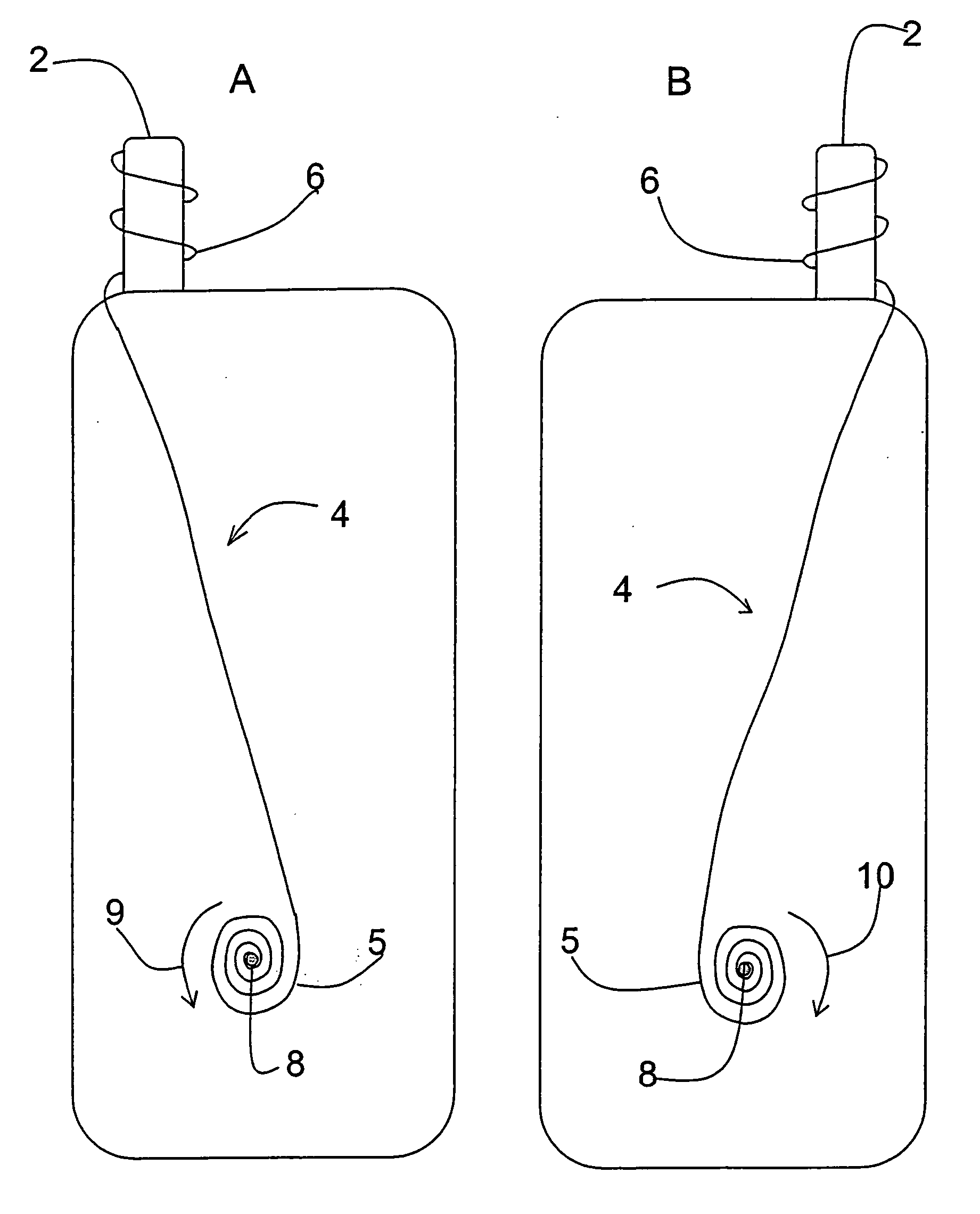
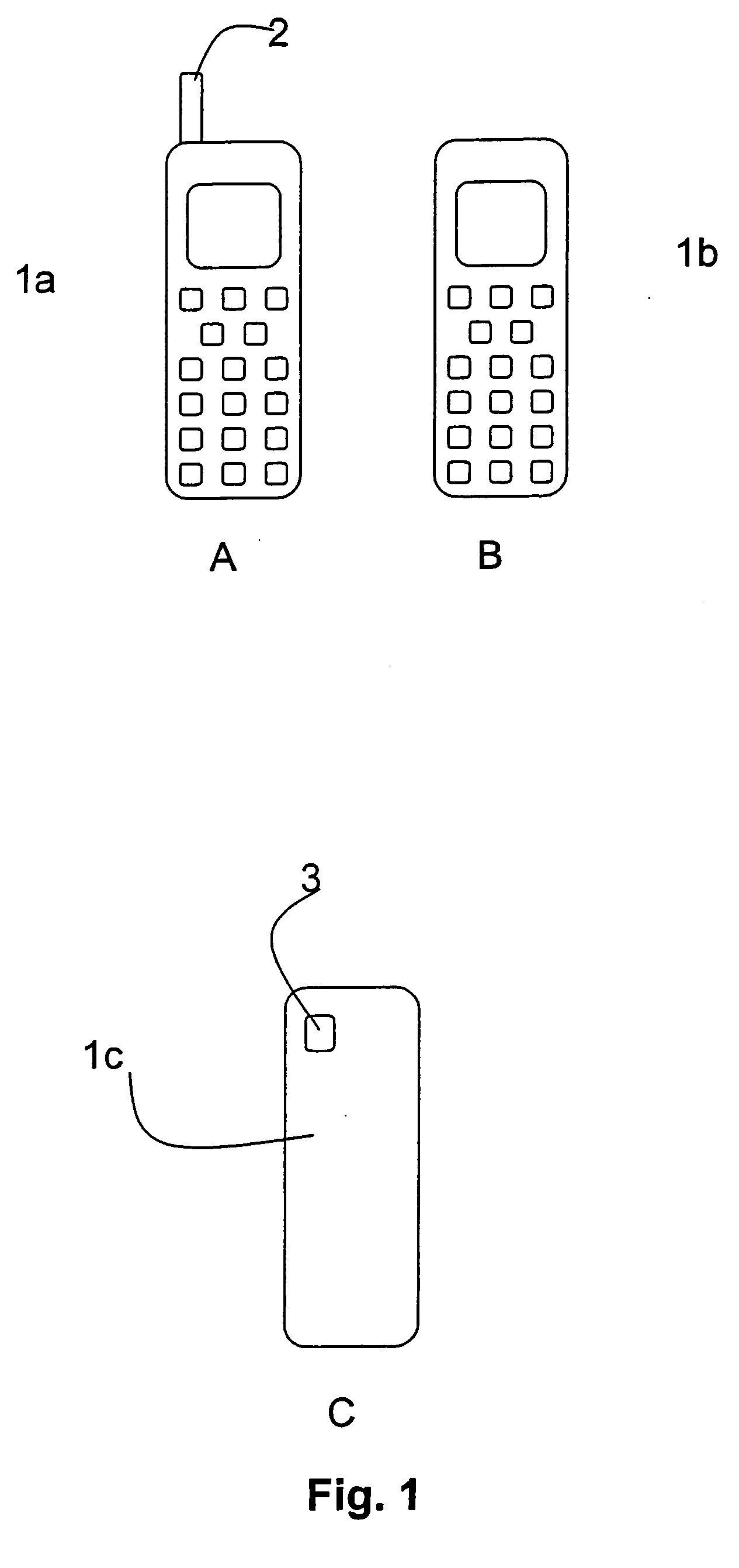
[0020]FIG. 1A shows a mobile phone a with an external antenna 2, and FIG. 1B shows a mobile phone b without an external antenna. These two types of mobile phones are the most frequently used types of mobile phones, and accordingly the description of the invention is focused on these two embodiments. However, the latter should not be understood in a limiting way because the shielding device according to the invention can also be used in connection with other electronic units including a built-in transmitter / receiver. The antenna 2 of the shown mobile phone a is arranged on the left side of the mobile phone, but it can also be arranged on the right side (not shown) of the mobile phone or at another location on the mobile phone, such as on the rear side or the front side, or on the side about the hinge in case the mobile phone is of the folding type. Other types of mobile phones b include an internal antenna, i.e the an...


PUM


Abstract

The invention relates to a device shielding especially an electronic unit with a transmitter, such as a mobile phone, against electromagnetic radiation. The device includes a crystal and an winding/spiral, where the winding/spiral is wound with the crystal arranged in the middle. One end of the winding extends immediately adjacent the antenna of the electronic unit. The device includes also a second winding of ferromagnetic material and a metallic film.

Description

TECHNICAL FIELD [0001] The invention relates to a device for shielding an electronic unit, especially an electronic unit including a transmitter, against electromagnetic radiation. BACKGROUND ART [0002] A few years ago the mobile phones were both expensive and unusual, and therefore the possible detrimental effects of the mobile phones were not in focus. Today, the latter attitude has changed, among other things because the majority of the population in many countries own both an ordinary land based phone at home and a mobile phone to take with them. Therefore, the question has been raised whether or not the electromagnetic radiation from the mobile phone can optionally have a detrimental effect on the body tissue, i.e. not only the radiation transmitted by the transmitter and the antenna, but also the radiation from the remaining components of the mobile phone, such as the microprocessor, the display etc. [0003] The radiation from the transmitter and the antenna of the mobile phone...

Claims


Application Information

Patent Timeline
Patent Type & Authority Applications(United States)
IPC IPC(8): H01Q1/24A61N1/16H01Q17/00H04B1/38H05K9/00
CPCH01Q1/245H01Q17/00H04B1/3838H05K9/0052A61N1/16
Inventor NEERGAARD, PER JANMADSEN, KARSTENZWEIDORFF, HANNAHBBOZZINI, RENE
Owner HANNAH B ZWEIDORFF
Why Eureka
Try Eureka