Vibratory transducer

a transducer and vibration technology, applied in direct mass flowmeters, liquid/fluent solid measurement, instruments, etc., can solve the problems of torsional vibrations being transmitted from the transducer, measurement inaccuracy, and damped torsional vibrations of the flow tube, so as to achieve simple and robust manner, simple vibration isolation, and largely keep away internal torques

Inactive Publication Date: 2006-01-05
ENDRESS HAUSER FLOWTEC AG
View PDF11 Cites 2 Cited by
  • Summary
  • Abstract
  • Description
  • Claims
  • Application Information

AI Technical Summary

Benefits of technology

[0023] One advantage of the invention lies in the fact that the transducer, despite possible operational variations in the density and / or viscosity of the fluid, is balanced in a simple and robust manner such that internal torques can be largely kept away from the connected pipe. Another advantage is that as a result of this constructionally very simple vibration isolation, the transducer according to the invention can be made very compact and very light.
lies in the fact that the transducer, despite possible operational variations in the density and / or viscosity of the fluid, is balanced in a simple and robust manner such that internal torques can be largely kept away from the connected pipe. Another advantage is that as a result of this constructionally very simple vibration isolation, the transducer according to the invention can be made very compact and very light.

Problems solved by technology

This results in the torsional vibrations of the flow tube being damped, so that additional excitation energy must be supplied to the flow tube to maintain those vibrations.
An essential disadvantage of the prior art transducers lies in the fact that in operation, torsional vibrations can be transmitted from the transducer via the flow tube and any transducer case that may be present to the connected pipe.
This, in turn, may result in a zero shift and, thus, in measurement inaccuracies.
Furthermore, the loss of vibrational energy to the transducer's environment may result in a substantial deterioration of efficiency and possibly also in a degradation of the signal-to-noise ratio in the measurement signal.

Method used


Image

  • Vibratory transducer
  • Vibratory transducer
  • Vibratory transducer

Examples


Embodiment Construction

[0032] While the invention is susceptible to various modifications and alternative forms, exemplary embodiments thereof have been shown by way of example in the drawings and will herein be described in detail. It should be understood, however, that there is no intent to limit the invention to the the particular forms diclosed, but on the contrary, the intention is to cover all modifications, equivalents, and alternatives falling within the spirit and scope of the invention as defined by the intended claims.

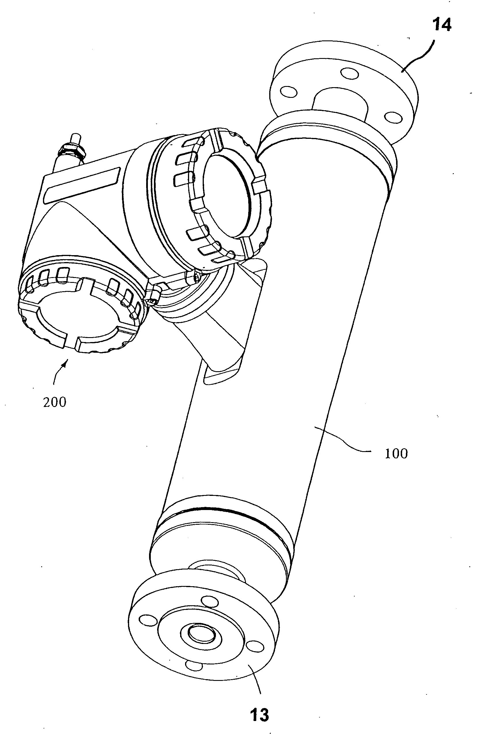
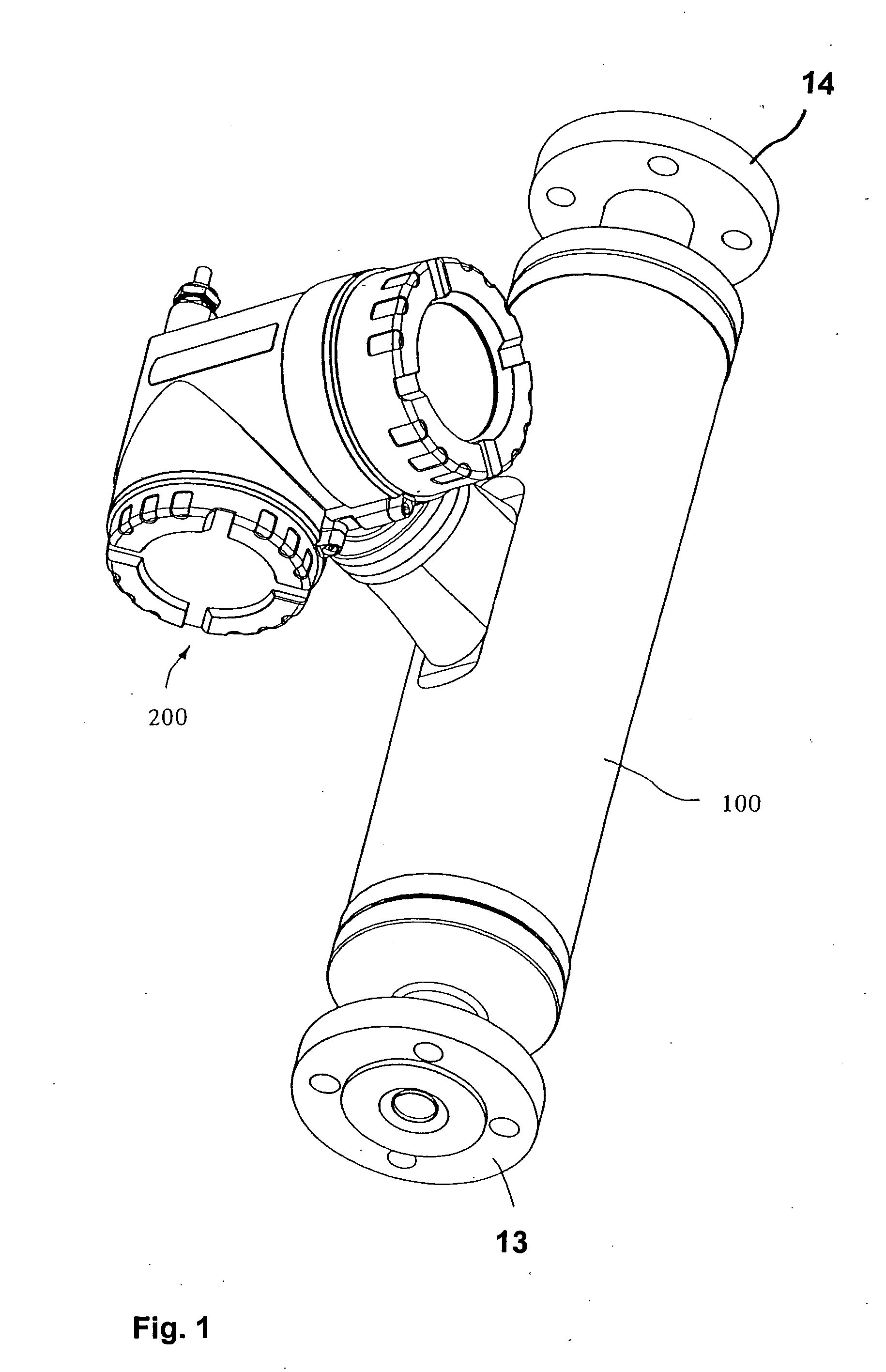
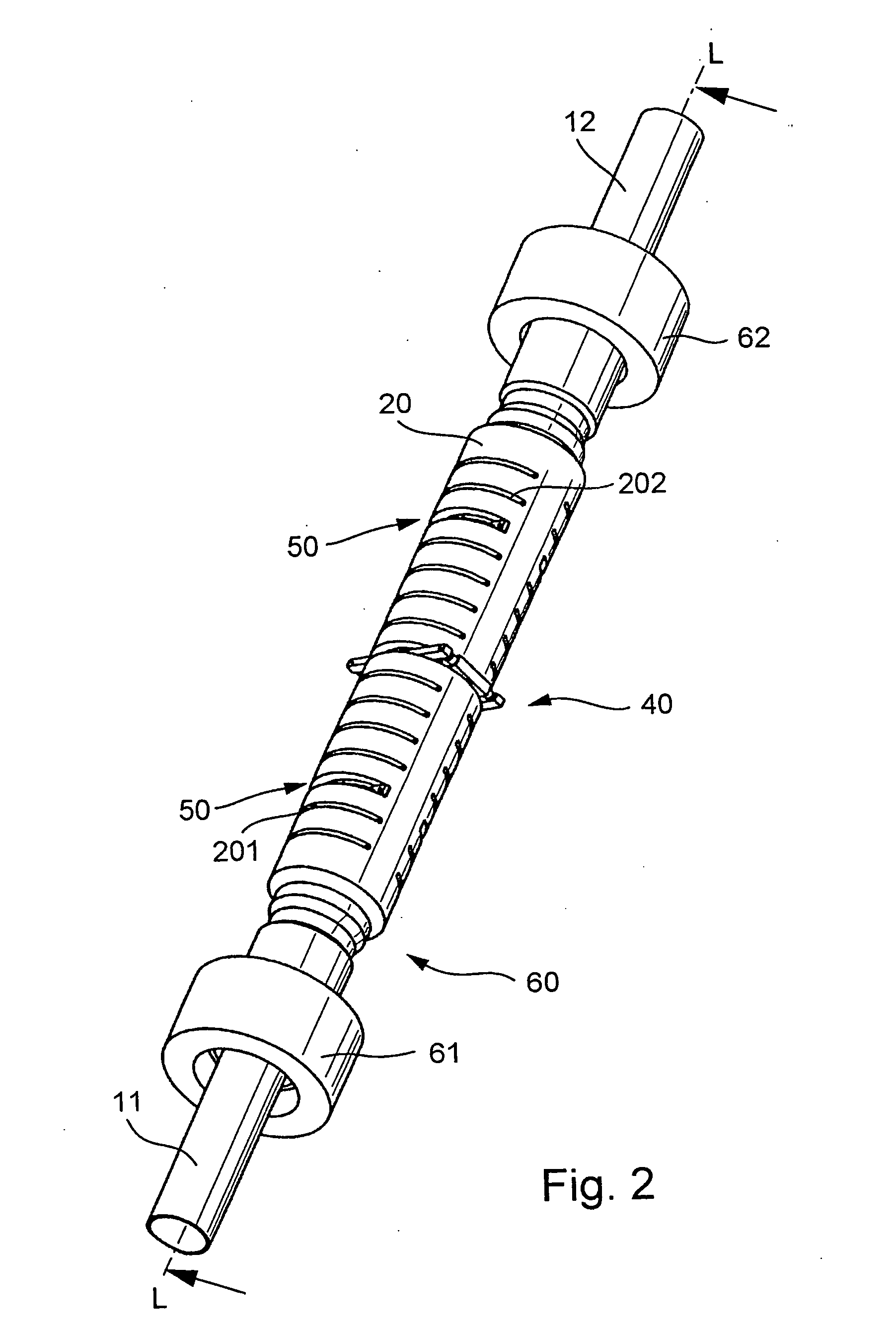
[0033]FIG. 1 shows a meter designed to be inserted in a pipe (not shown) for measuring the viscosity of a fluid flowing in the pipe. In addition, the meter may also designed to measure the mass flow rate and / or the density of the fluid. It comprises a vibratory transducer through which the fluid to be measured flows in operation. FIGS. 2 to 6 show schematically embodiments and developments of such vibratory transducers.

[0034] To conduct the fluid, the transducer comprises an ess...


PUM

PropertyMeasurementUnit
resonance frequencyaaaaaaaaaa
lengthaaaaaaaaaa
wall thicknessaaaaaaaaaa

Abstract

To conduct a fluid, the transducer has a flow tube which in operation is vibrated by an excitation assembly and whose inlet-side and outlet-side vibrations are sensed by means of a sensor arrangement. To produce shear forces in the fluid, the flow tube is at least intermittently excited into torsional vibrations about a longitudinal flow-tube axis. The transducer further comprises a torsional vibration absorber which is fixed to the flow tube and which in operation covibrates with the torsionally vibrating flow tube, thus producing reactive torques which at least partially balance torques developed in the vibrating flow tube. One of the advantages of the transducer disclosed is that it is dynamically balanced to a large extent even in the face of variations in fluid density or viscosity.

Description

FIELD OF THE INVENTION [0001] This invention relates to a vibratory transducer which is particularly suited for use in a viscometer, a viscometer-densimeter, or a viscometer-mass flowmeter. BACKGROUND OF THE INVENTION [0002] To determine the viscosity of a liquid flowing in a pipe, use is frequently made of meters which, using a vibratory transducer, comprising a flow tube communicating with the pipe, and control and evaluation electronics connected thereto, induce shear or friction forces in the fluid and derive therefrom a measurement signal representing the viscosity. [0003] U.S. Pat. No. 4,524,610, U.S. Pat. No. 5,253,533, U.S. Pat. No. 6,006,609, or EP-A 1 158 289, for example, disclose in-line viscometers, i.e., viscometers connectable into a fluid-conducting pipe, with a vibratory transducer which responds to the viscosity of the fluid flowing in the pipe and comprises: [0004] a single straight flow tube for conducting the fluid which vibrates in operation and communicates wi...

Claims


Application Information

Patent Timeline
Patent Type & Authority Applications(United States)
IPC IPC(8): G01F1/84G01N3/00G01N9/00G01N11/16
CPCG01F1/8409G01F1/8413G01F1/8418G01F1/8422G01F1/8427G01N2203/0676G01N9/002G01N11/167G01N2203/0025G01N2203/0094G01F1/849
Inventor RIEDER, ALFREDDRAHM, WOLFGANG
Owner ENDRESS HAUSER FLOWTEC AG
Why Eureka
Try Eureka