

Optical system with wavelength selecting device
a wavelength selection and optical system technology, applied in the field of optical systems with wavelength selection devices, can solve the problems of inability to improve optical performance, inability to meet the requirements of chromatic aberration correction without increasing liable to incur increase in the thickness of lens elements and the number of lens elements, so as to achieve high optical performance, low manufacturing cost, and compact
- Summary
- Abstract
- Description
- Claims
- Application Information
AI Technical Summary
Benefits of technology
Problems solved by technology
Method used
Image

Examples
first embodiment
[First Embodiment]
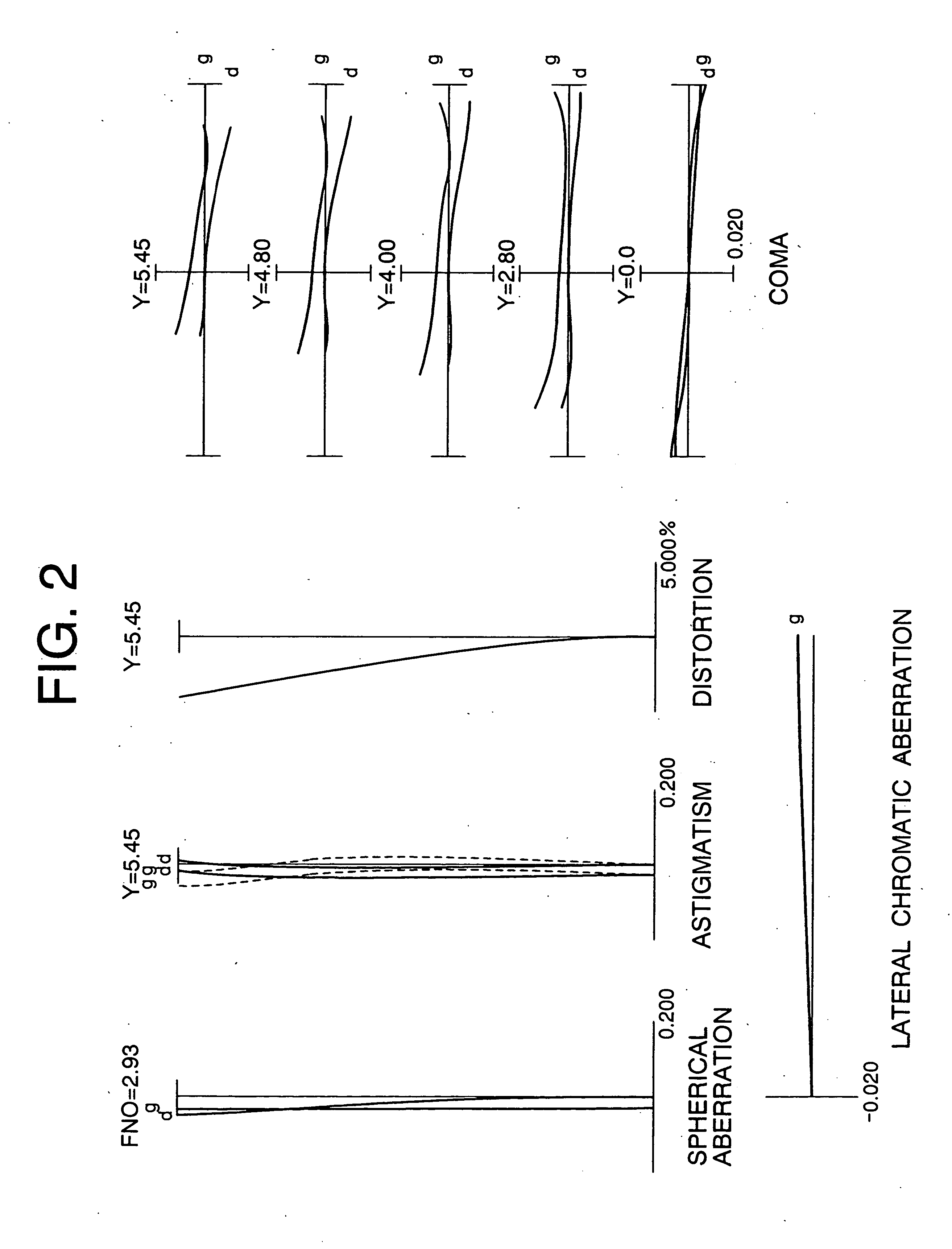
At first, a first embodiment of the present invention having a wavelength selecting device, precisely described later, is explained below with reference to accompanying drawings. FIG. 1 is a sectional view showing the lens arrangement of an optical system according to Example 1 of a first embodiment of the present invention in a wide-angle end state W and in a telephoto end state T. Various aberrations of the objective optical system OB according to Example 1 of a first embodiment in the wide-angle end state and in the telephoto end state are shown in FIGS. 2 and 3, respectively. As is shown in FIGS. 2 and 3, monochromatic aberrations are satisfactorily corrected, but lateral chromatic aberration is somewhat remained. This lateral chromatic aberration written in the form relative to the wavelength is shown in FIGS. 4 and 5. According to the graphs, since a large amount of lateral chromatic aberration is produced in a short wavelength side, if this portion of aberr...
example 1
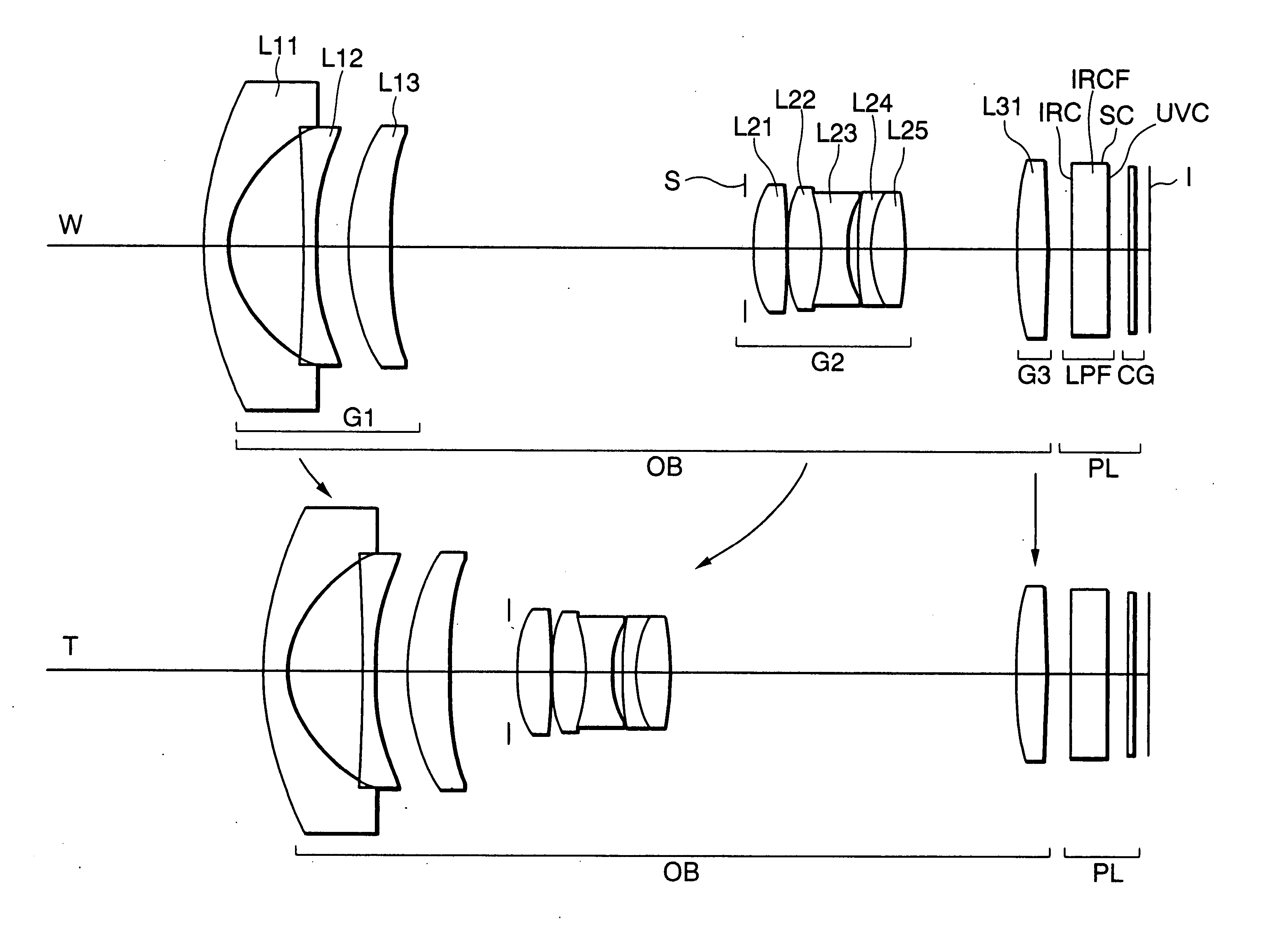
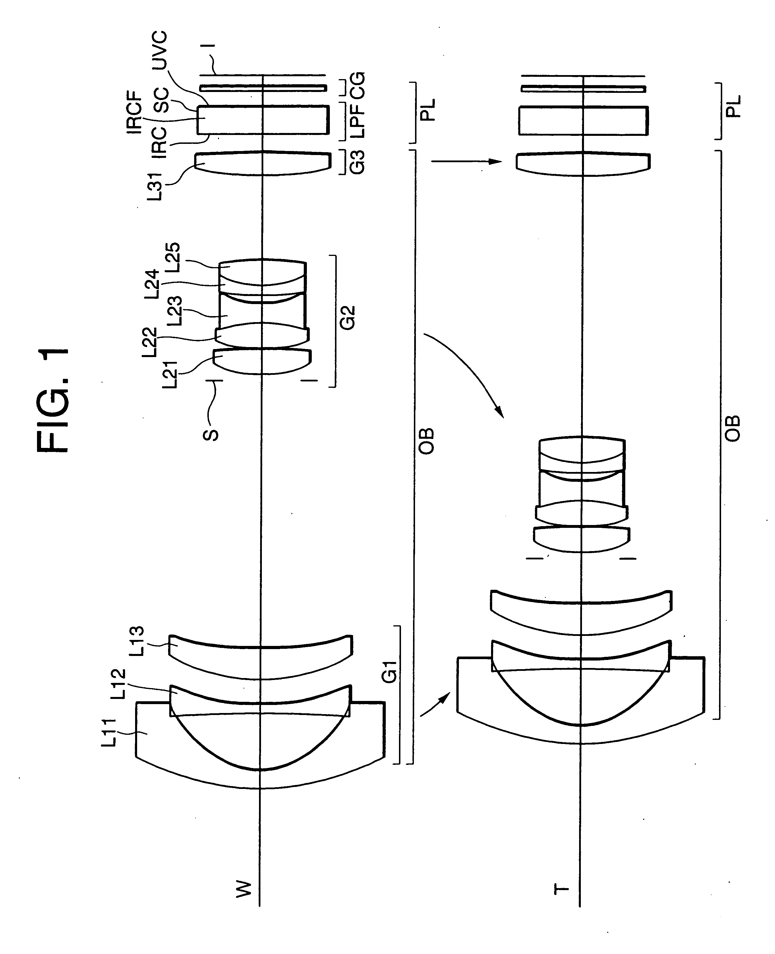
FIG. 1 is a sectional view showing the lens arrangement of an optical system according to Example 1 of a first embodiment of the present invention in a wide-angle end state W and a telephoto end state T.
The optical system with a wavelength selecting device according to Example 1 is composed of, in order from an object side along the optical axis, an objective optical system OB, a no-power optical group PL, and an imaging device I.
The objective optical system OB is composed, in order from the object along the optical axis, a first lens group G1, a second lens group G2 including an aperture stop S, and a third lens group G3.
The first lens group G1 having negative refractive power as a whole is composed of, in order from the object, a negative meniscus lens L11 having a convex surface facing to the object and an aspherical surface facing to an image, a double concave negative lens L12 having a stronger concave surface facing to the image, and a positive meniscus lens L13 having a...
example 2
FIG. 12 is a sectional view showing the lens arrangement of an optical system according to Example 2 of the first embodiment of the present invention in a wide-angle end state W and in a telephoto end state T.
The optical system with a wavelength selecting device according to Example 2 is composed of, in order from an object side along the optical axis, an objective optical system OB, a no-power optical group PL, and an imaging device I.
The objective optical system OB is composed, in order from the object along the optical axis, a first lens group G1, a second lens group G2 including an aperture stop S, and a third lens group G3. The objective optical system OB according to Example 2 is the same as that of Example 1, so that a duplicated explanation is abbreviated.
The no-power optical group PL arranged to the image side of the objective optical system OB is composed of, in order from the object, a low-pass filter LPF having a plane-parallel shape with no refractive power, and a...
PUM
 Abstract
Description
Claims
Application Information