Apparatus and method for linearizing adaptive array antenna system

a technology of array antennas and antennas, applied in diversity/multi-antenna systems, digital transmission, baseband system details, etc., can solve the problems of increasing the manufacturing cost corresponding to the number of array antennas, the limitation of improving the performance and capacity of mobile communication systems, and the inability of conventional mobile communication technology to provide mobile communication services. , to achieve the effect of reducing the complexity of hardwar

Inactive Publication Date: 2006-06-22
ELECTRONICS & TELECOMM RES INST
View PDF8 Cites 38 Cited by
  • Summary
  • Abstract
  • Description
  • Claims
  • Application Information

AI Technical Summary

Benefits of technology

[0013] It is, therefore, an object of the present invention to provide an adaptive array antenna system linearizing each transmitting channel by using a feed-back path identical with a feed-b...

Problems solved by technology

There is a limitation for improving a performance and capacity of mobile communication system due to wireless channel characteristics such as co-channel interference signal and path loss generated inner cell or between cells, multipath fading, signal delay and Doppler effect and shadow area.
Therefore, it is expected that conventional mobile communication technology could not provide the mobile communication service to sati...

Method used


Image

  • Apparatus and method for linearizing adaptive array antenna system
  • Apparatus and method for linearizing adaptive array antenna system
  • Apparatus and method for linearizing adaptive array antenna system

Examples


Embodiment Construction

[0022] Other objects and aspects of the invention will become apparent from the following description of the embodiments with reference to the accompanying drawings, which is set forth hereinafter.

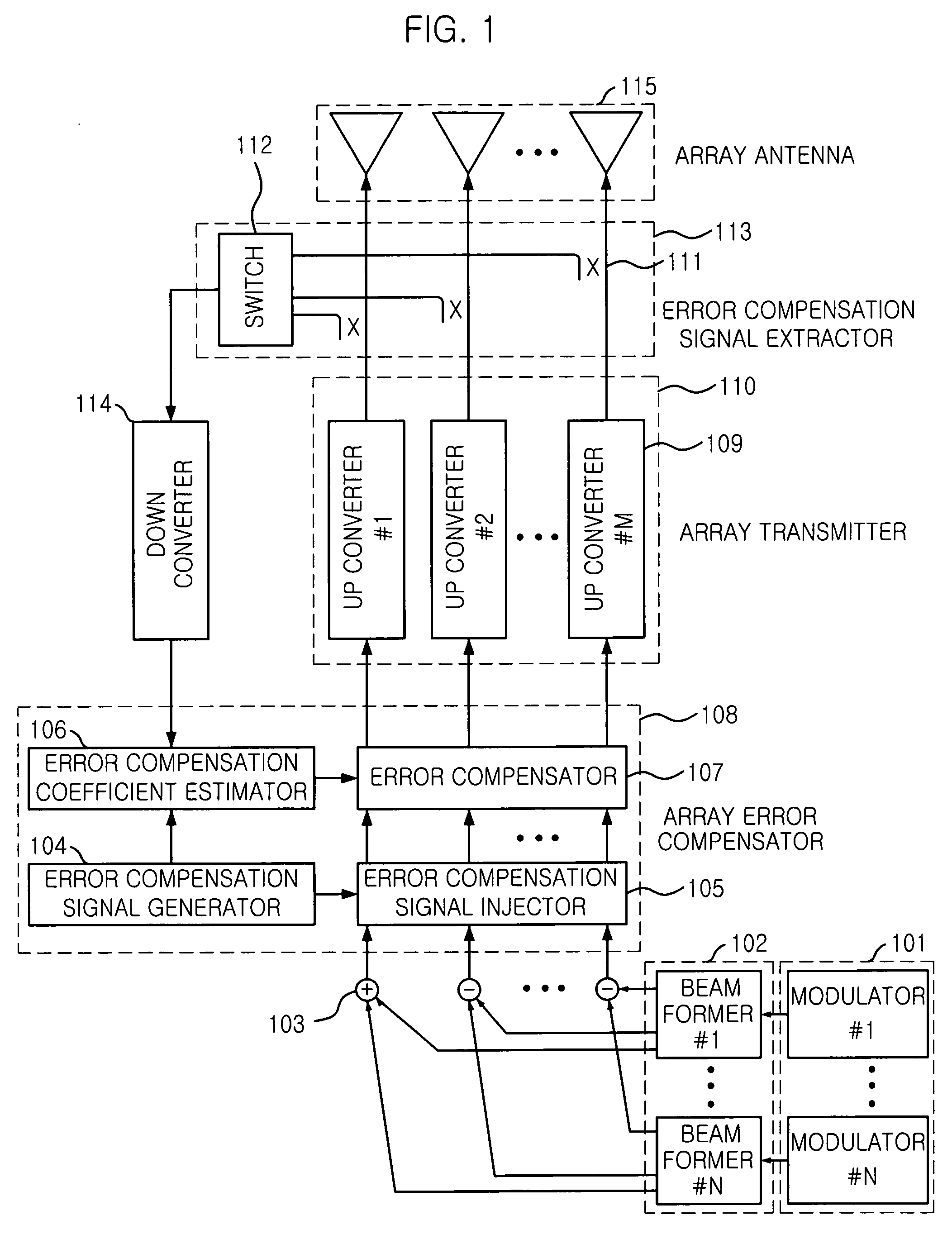
[0023]FIG. 1 is a diagram illustrating a conventional adaptive array antenna system having a function of error compensation.

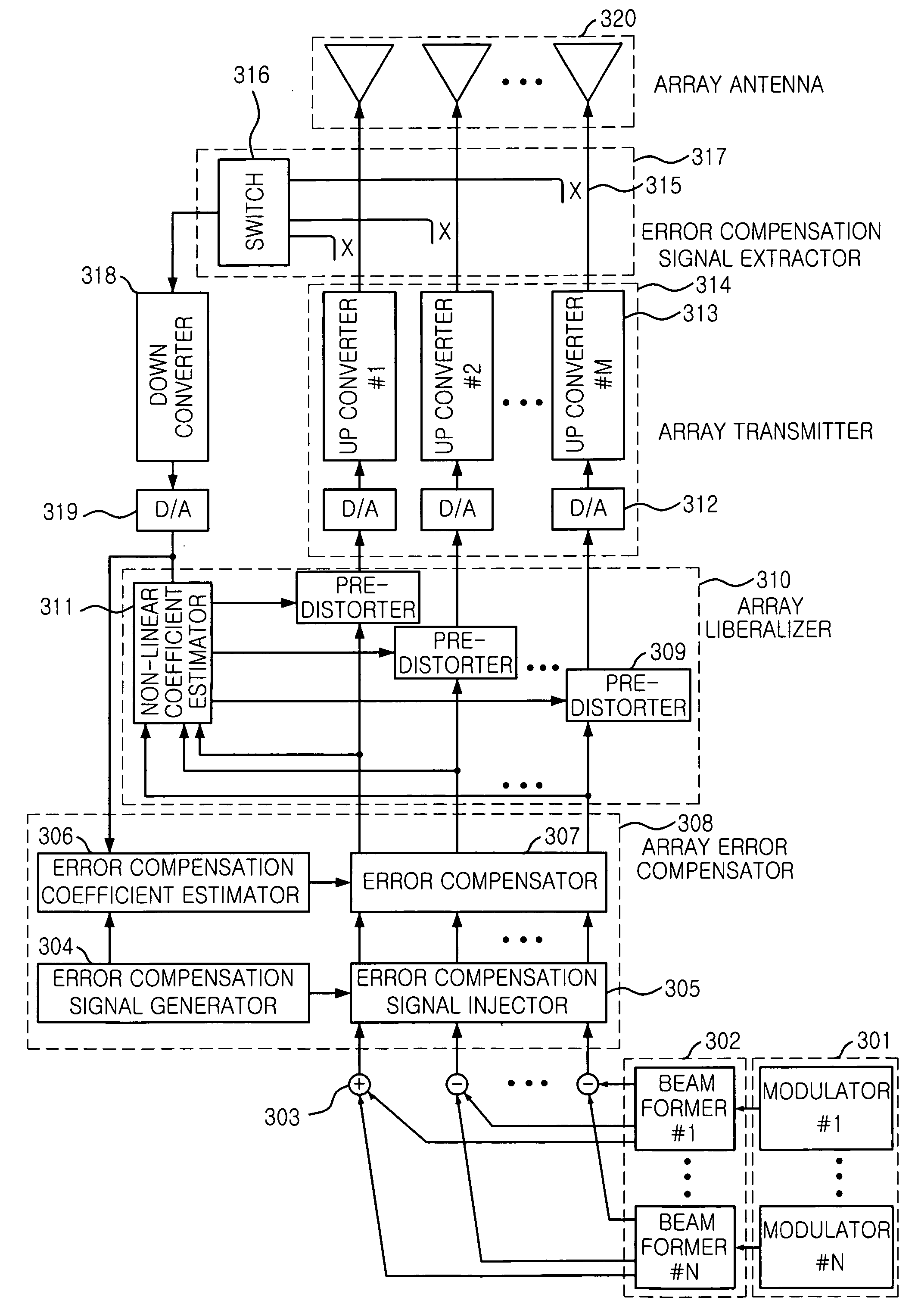
[0024] Referring to FIG. 1, the conventional adaptive array antenna system includes a modulator unit 101 having a plurality of modulators for generating transmitting data corresponding to the number of users; a beamforming unit 102 having a plurality of beamformers for multiplexing the generated transmitting data with a beamforming weight and transferring a result of multiplexing to vector adders 103; the vector adders 103 for adding each output of beamformers in beam forming unit 102 corresponding to each user and transferring results of vector adders 103 to an error compensator 108; the error compensator 108 for multiplexing transmitting data with a reverse of tra...


PUM


Abstract

Disclosed is an apparatus and method for linearizing an adaptive array antenna system. The apparatus and method for linearizing an adaptive array antenna system uses an identical feedback path as feedback path for estimation of a transfer function and a feedback path for linearization of each transmission channel in a multi-channel transmitter, thereby reducing hardware complexity of an adaptive array transmitter.

Description

TECHNICAL FIELD [0001] The present invention relates to an adaptive array antenna system linearizing each transmitting channel of a multichannel transmitter by using identical feed-back path used for an error compensation method measuring a transfer function by feed-backing transmitting signal of each transmission channel at multi-channel transmitter and a method thereof. BACKGROUND ART [0002] There is a limitation for improving a performance and capacity of mobile communication system due to wireless channel characteristics such as co-channel interference signal and path loss generated inner cell or between cells, multipath fading, signal delay and Doppler effect and shadow area. For overcoming the limitation, various compensation techniques have been introduced such as power control, channel coding, RAKE receiving, diversity antenna, cell secterization, distribution of frequency and spread spectrum. Recently, the number of users using the mobile communication service has been incr...

Claims


Application Information

Patent Timeline
IPC IPC(8): H04L25/03H04L27/04H01Q3/26H01Q21/00H04B7/06H04L27/36
CPCH01Q3/267H04B7/0617H04L27/368H01Q21/00
Inventor JUNG, JAE-HOLYU, DEUK-SUOH, HYUN-SEO
Owner ELECTRONICS & TELECOMM RES INST
Why Eureka
Try Eureka