Apparatus for the measuring of fluid levels and pumping of the same

Inactive Publication Date: 2006-06-22
HILL DAVID R +1
View PDF2 Cites 4 Cited by
  • Summary
  • Abstract
  • Description
  • Claims
  • Application Information

AI Technical Summary

Benefits of technology

[0074] compressing fluid within the gas compression chamber to obtain a compressed fluid with the first valve closed to prevent evacuation of the fluid fro

Problems solved by technology

Of course, this is often unsatisfactory for several reasons.
First, running the pump constantly or at too great a speed is inefficient since, some of the time, the well bore is completely empty and there is nothing to pump.
Second, the equipment is subject to wear and damage resulting in costly repairs when pumps are run dry.

Method used


Image

  • Apparatus for the measuring of fluid levels and pumping of the same
  • Apparatus for the measuring of fluid levels and pumping of the same
  • Apparatus for the measuring of fluid levels and pumping of the same

Examples


Embodiment Construction

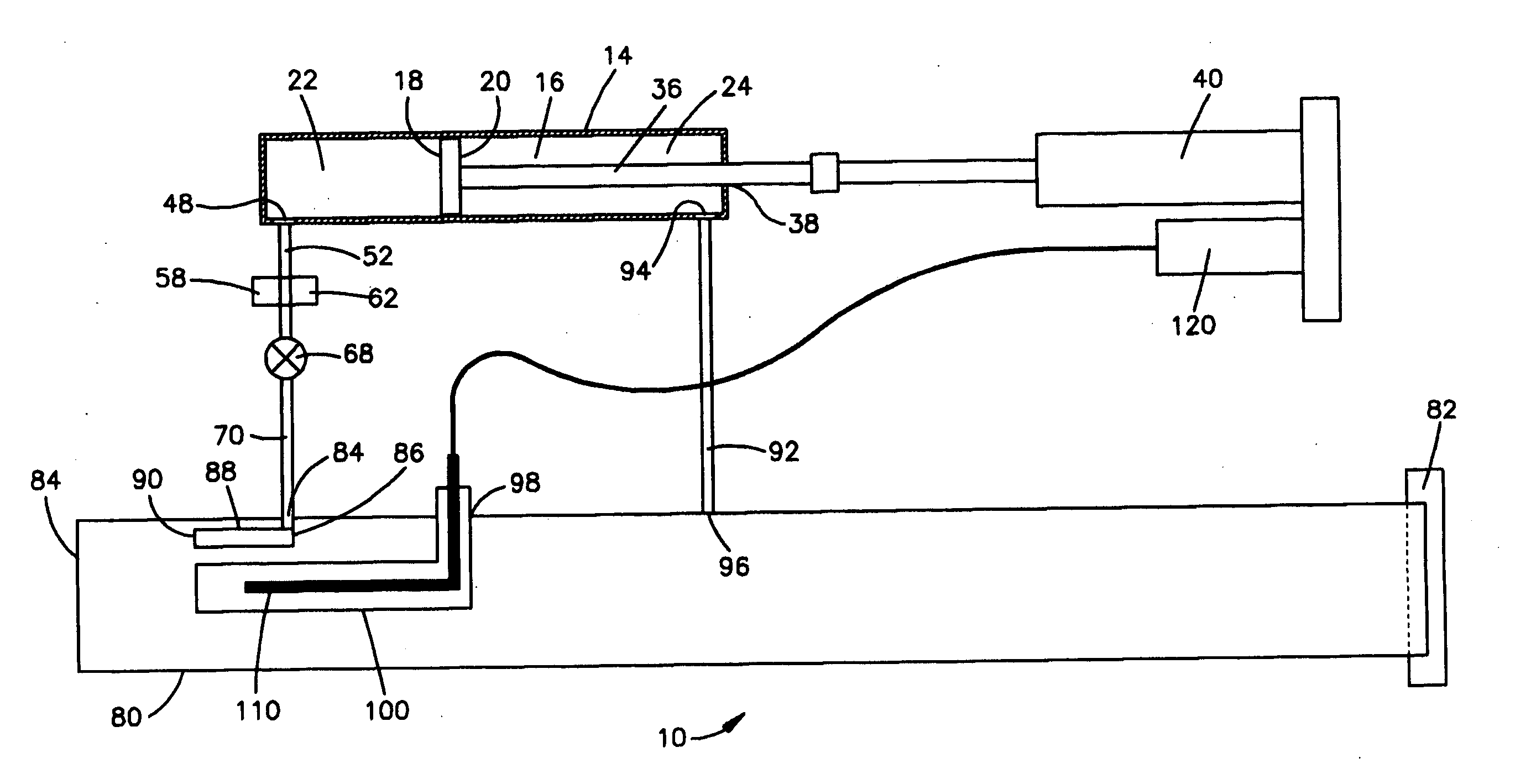
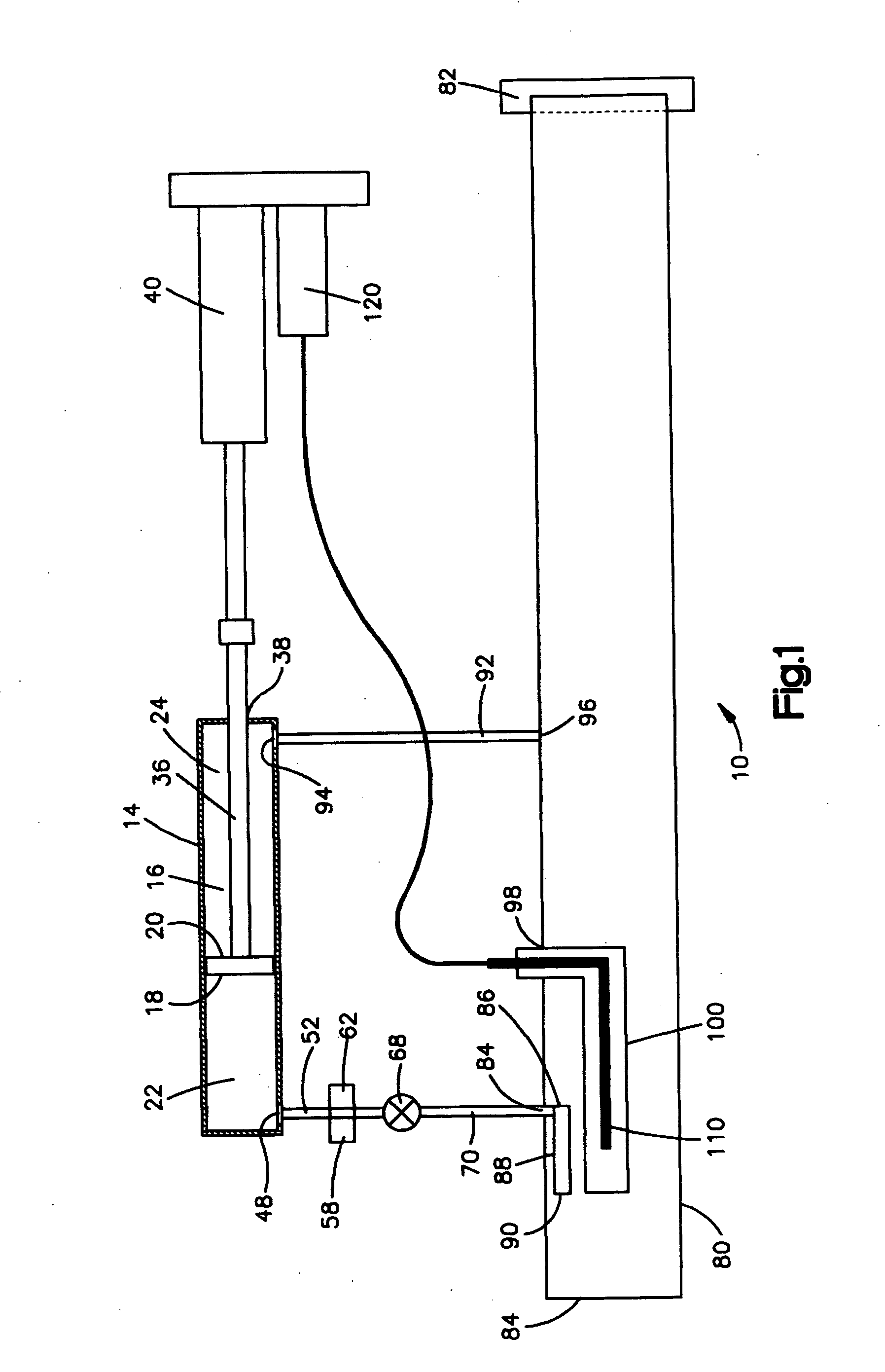
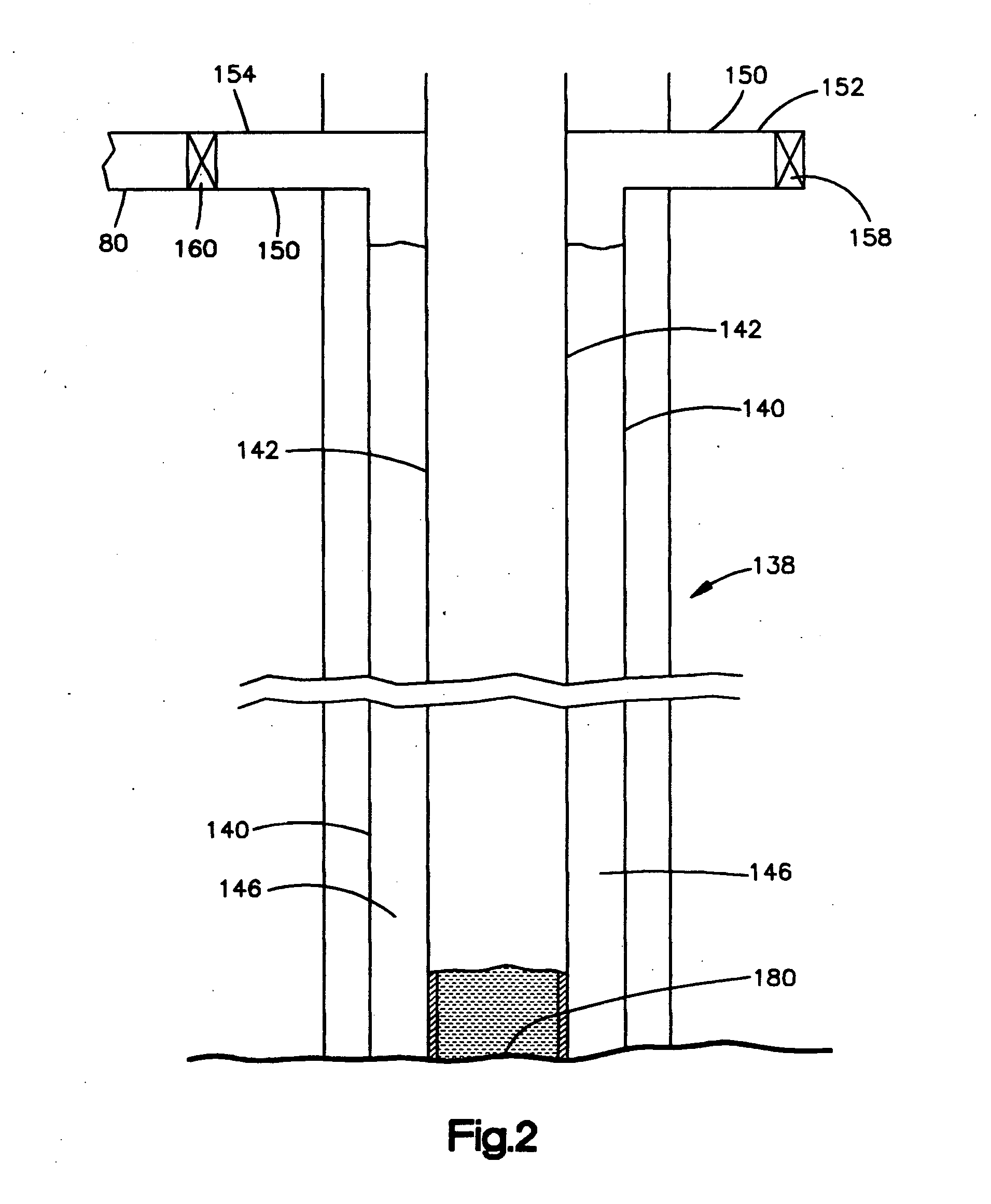
[0092] A pump controlling device 10 for controlling pump conditions in a well is shown in FIG. 1. The pump controlling device 10 is connected with well 12 as seen in FIG. 2. The pump controlling device 10 comprises a gas compression chamber shown herein as a piston chamber 14. A piston 16 is located within the piston chamber 14. The piston 16 has a piston front face 18 and a piston rear face 20. The term compression chamber herein means any suitable means of compressing a gas.

[0093] The piston chamber 14 has a piston fore chamber 22 located on the side of the piston chamber 14 adjacent to the piston front face 18. The piston 16 forms an airtight seal to prevent fluid communication between the piston front face 18 and the piston rear face 20. The piston chamber 14 has a piston after chamber 24 located on the side of the piston chamber 14 adjacent to the piston rear face 20.

[0094] The piston 16 has a piston stem 36. The piston stem 36 extends axially in after chamber 24 and extends ...


PUM


Abstract

A device for employing sonic transmissions is utilized to determine fluid level in a well or a container. The device may be utilized while the well is operating. It is known that wells replenish fluid at different rates even in the same formation or well field. Increased well production at minimum pumping cost is achieved for a given well.

Description

BACKGROUND OF THE INVENTION [0001] 1. Field of the Invention [0002] The present invention relates to determining the level of a fluid in a well such as a gas well, an oil well, or water well. [0003] 2. Description of the Art Practices [0004] It is known that wells replenish fluids at different rates even in the same formation or well field. The rate of fluid flow into the well bore is maximized because the hydrostatic head driving the fluid is at a maximum. See for example Burris, et al., U.S. Pat. No. 6,085,836 issued Jul. 11, 2000. The Burris, et al., patent is incorporated herein by reference. [0005] The preceding observation suggests that the well pump should run constantly to keep the level in the well bore as low as possible thus maximizing production. Of course, this is often unsatisfactory for several reasons. [0006] First, running the pump constantly or at too great a speed is inefficient since, some of the time, the well bore is completely empty and there is nothing to pum...

Claims


Application Information

Patent Timeline
IPC IPC(8): H04R17/02
CPCG01F23/296
Inventor HILL, DAVID R.BURRIS, SANFORD A.
Owner HILL DAVID R
Why Eureka
Try Eureka