Photo-detector, space information detection device using the photo-detector, and photo-detection method

A photoelectric detector and photoelectric conversion technology, applied in the direction of optical devices, measuring devices, photometry, etc., can solve the problems of difficulty in obtaining signal-to-noise ratio, reduction of dynamic range, and inability to extract a large amount of received light output from signal light.

Inactive Publication Date: 2009-10-28
MATSUSHITA ELECTRIC WORKS LTD
View PDF5 Cites 0 Cited by
  • Summary
  • Abstract
  • Description
  • Claims
  • Application Information

AI Technical Summary

Problems solved by technology

Therefore, there is a problem that the control becomes complicated to obtain the received light output within an appropriate range by suppressing the dynamic range of the received light amount
However, in the presence of ambient light, the dynamic range of the signal light from the photodetector is reduced
When the photodetector is saturated, there is still the problem of not being able to extract a large amount of received light output for the signal light
In short, in the presence of ambient light, even when the amount of light emitted from the light emitting source is increased, or the light receiving time of the photodetector is prolonged, since the dynamic range of the signal light for the photodetector is reduced, and It is difficult to obtain a large enough signal-to-noise ratio

Method used


Image

  • Photo-detector, space information detection device using the photo-detector, and photo-detection method
  • Photo-detector, space information detection device using the photo-detector, and photo-detection method
  • Photo-detector, space information detection device using the photo-detector, and photo-detection method

Examples


no. 1 example

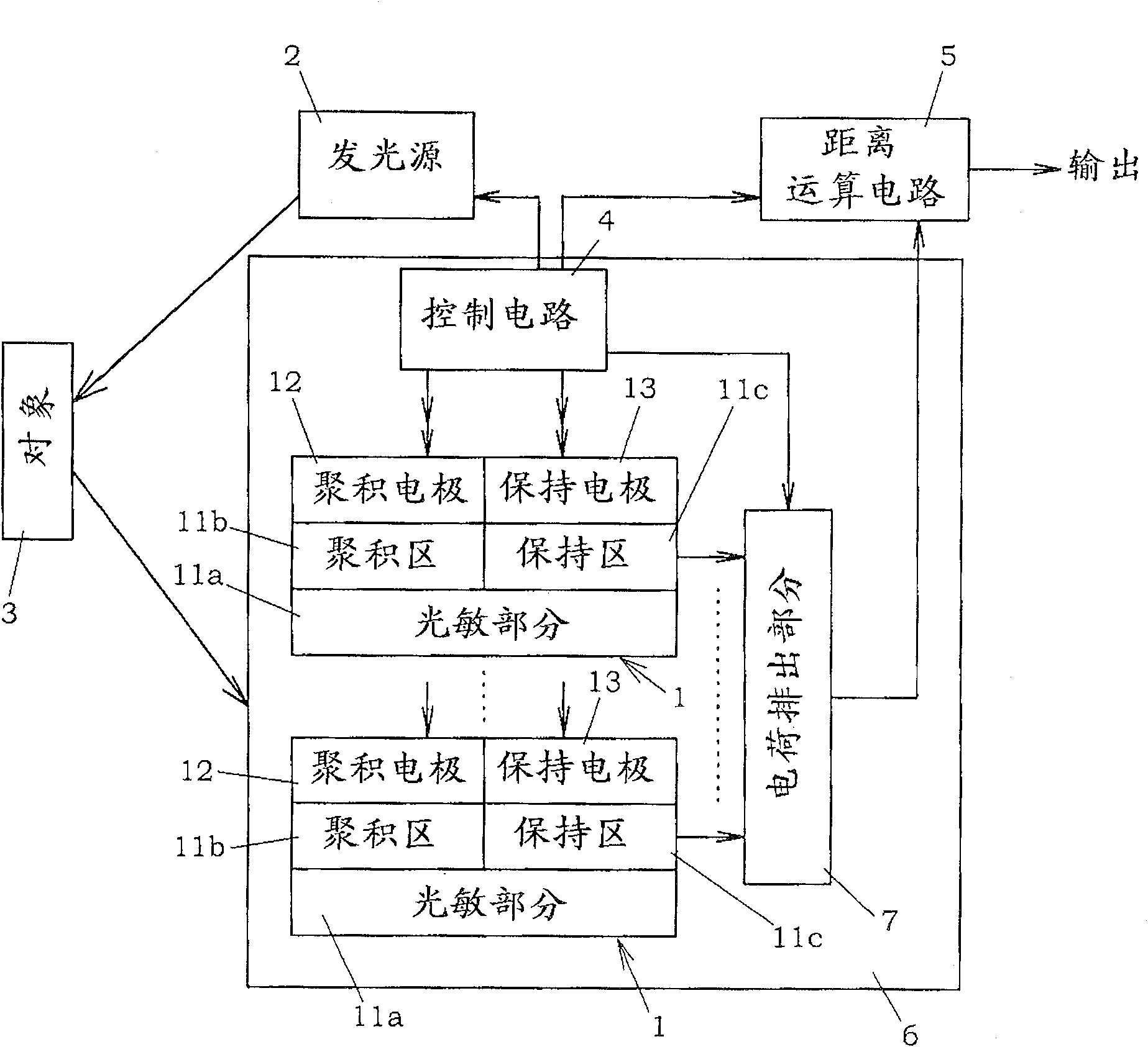
[0068] figure 1 Shown is a distance measuring device, which is a spatial information detecting device using the photodetector 6 of this embodiment. In this distance measuring device, light is projected from a light emitting source 2 to a target space including an object 3 to be measured, and a photodetector 6 receives light including light reflected on the object from the target space, so as to obtain from the photodetector 6 a The received light output of the light quantity of reflected light. In order to measure the distance to the object by this configuration, a technique using the principle of triangulation, or a technique of measuring the flight time of light from the light emitting source 2 to the photodetector 6 is mainly utilized.

[0069] When the principle of triangulation is used, a parallel light beam of a predetermined pattern is projected from the light emitting source 2 to the target space, and the projected pattern on the target 3 is received by the photodetec...

no. 2 example

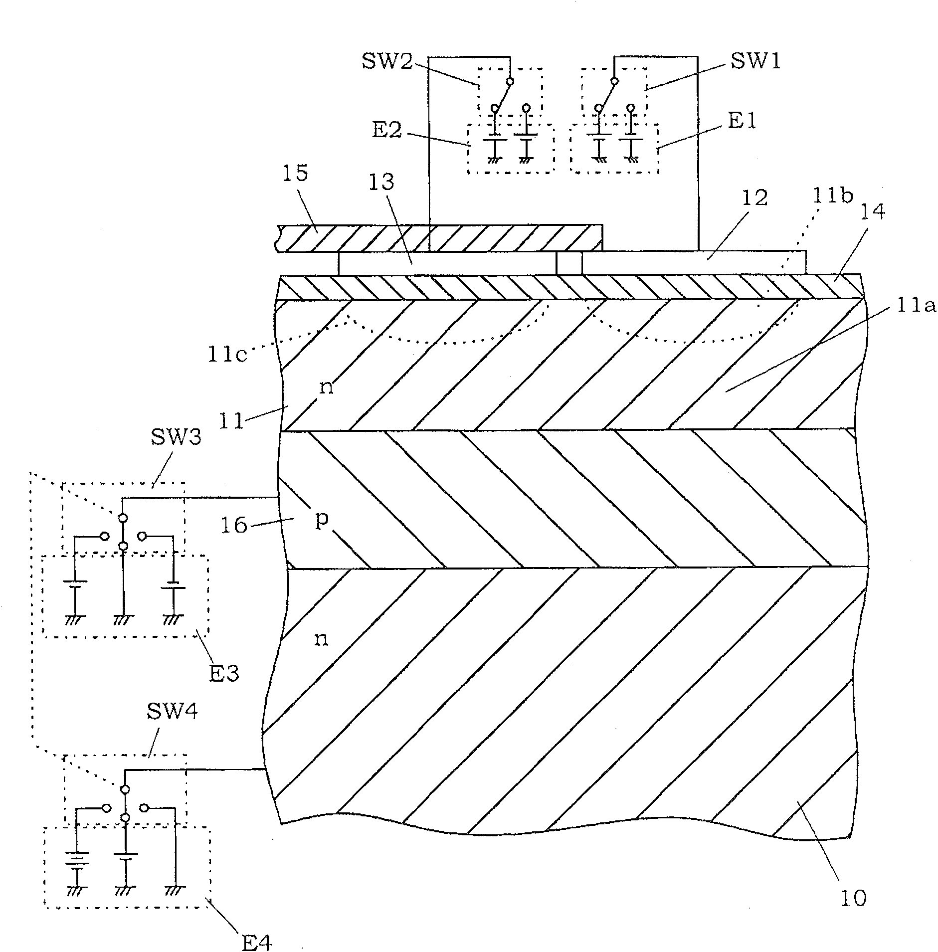
[0138] Such as Figure 6 As shown, the present embodiment is characterized in that two accumulation electrodes (12a, 12b) and two sustain electrodes (13a, 13b) are formed for each of the photoelectric conversion portions 1. That is, two accumulation electrodes (12a, 12b) and two sustain electrodes (13a, 13b) are defined as one group (or one pixel). Two sustaining electrodes (13a, 13b) are arranged spaced apart from each other. Two accumulating electrodes (12a, 12b) are arranged between the holding electrodes (13a, 13b). In addition, the accumulation electrodes (12a, 12b) are separated from each other by a gap "g", which is greater than the distance between each of the accumulation electrodes (12a, 12b) and the adjacent sustaining electrodes (13a, 13b). In this configuration, light is incident on the photosensitive portion 11a through the aperture between the light-shielding films 15 for covering the holding electrodes (13a, 13b). Additionally, if Figure 7 As shown, the li...

no. 3 example

[0170] In the second embodiment, since the gap "g" becomes wider, electrons and holes can be easily separated. In the case where the photodetector 6 is formed by arranging a plurality of photoelectric conversion parts 1 and the main functional layer 11 is also used as a vertical transfer transistor, since the accumulation electrodes (12a, 12b) and the holding electrodes (13a, 13b) ) and the potential well formed in the main functional layer 11 to transport carriers (electrons or holes), so there is a concern that when the gap "g" is excessively increased, the part for the gap "g" cannot be formed for Potential well for transporting charge carriers.

[0171] Such as Figure 9A As shown, this embodiment is characterized by the formation of the transfer electrode 22 between the accumulation electrodes (12a, 12b). In this case, there is an advantage that electrons and holes are easily separated by increasing the distance between accumulation electrodes (12a, 12b), and also it is...


PUM


Abstract

Provided is a photodetector capable of stably obtaining a photodetection output by preventing reduction in the dynamic range of signal light even under conditions of sufficient ambient light. The photodetector includes: an accumulation electrode and a sustain electrode, which are arranged on the photoelectric conversion unit through an insulating layer; and a control unit for controlling the timing of applying voltages to the electrodes and the polarity of the voltages. One of electrons or holes generated in the photoelectric conversion portion is accumulated in an accumulation region formed by applying a voltage to the accumulation electrode, and the other is accumulated in a holding region formed by applying a voltage to the holding electrode. Then, the electrons and holes in the accumulation region and the holding region are recombined, and the remaining electrons or holes that are not recombined are output.

Description

technical field [0001] The present invention relates to a technique for stably obtaining a received light output with respect to signal light as a detection object even in the presence of sufficient ambient light such as natural light from the sun and indoor lighting. Background technique [0002] In the past, various photodetectors such as photodiodes, phototransistors, and CCD image sensors were well known and widely used in the following applications: photosensors, which detect the presence or absence of objects based on changes in the amount of light received; optical communications, which use Light as a transmission medium; distance sensors for optically measuring distances by using the principle of triangulation or the time difference or phase difference between projected and received light; and image pickup devices for video and digital cameras. [0003] In such a photodetector, when the received light amount is within an appropriate range, a received light output hav...

Claims


Application Information

Patent Timeline
Patent Type & Authority Patents(China)
IPC IPC(8): H01L31/10G01B11/00G01J1/02G01S17/32G01S17/89H01L27/146H01L27/148H01L31/00H03K17/945H04N5/335H04N5/355H04N5/369H04N5/372H04N5/376
Inventor 桥本裕介高田裕司
Owner MATSUSHITA ELECTRIC WORKS LTD
Why Eureka
Try Eureka