Hole assisted fiber device and fiber preform

a technology of optical fiber and preform, which is applied in the direction of cladding optical fibre, manufacturing tools, instruments, etc., can solve the problems of high attenuation, high manufacturing cost, and high hole roughness, and achieve the effect of reducing the cost of manufacturing, and improving the quality of optical fiber

Inactive Publication Date: 2006-06-22
3M INNOVATIVE PROPERTIES CO
View PDF25 Cites 73 Cited by
  • Summary
  • Abstract
  • Description
  • Claims
  • Application Information

AI Technical Summary

Benefits of technology

[0010] The above summary of the present invention is not intended to describe each illustrated embodiment or every implementatio

Problems solved by technology

However, these techniques create problems with cleanliness, hole roughness, strength, high attenuation,

Method used


Image

  • Hole assisted fiber device and fiber preform
  • Hole assisted fiber device and fiber preform
  • Hole assisted fiber device and fiber preform

Examples


examples

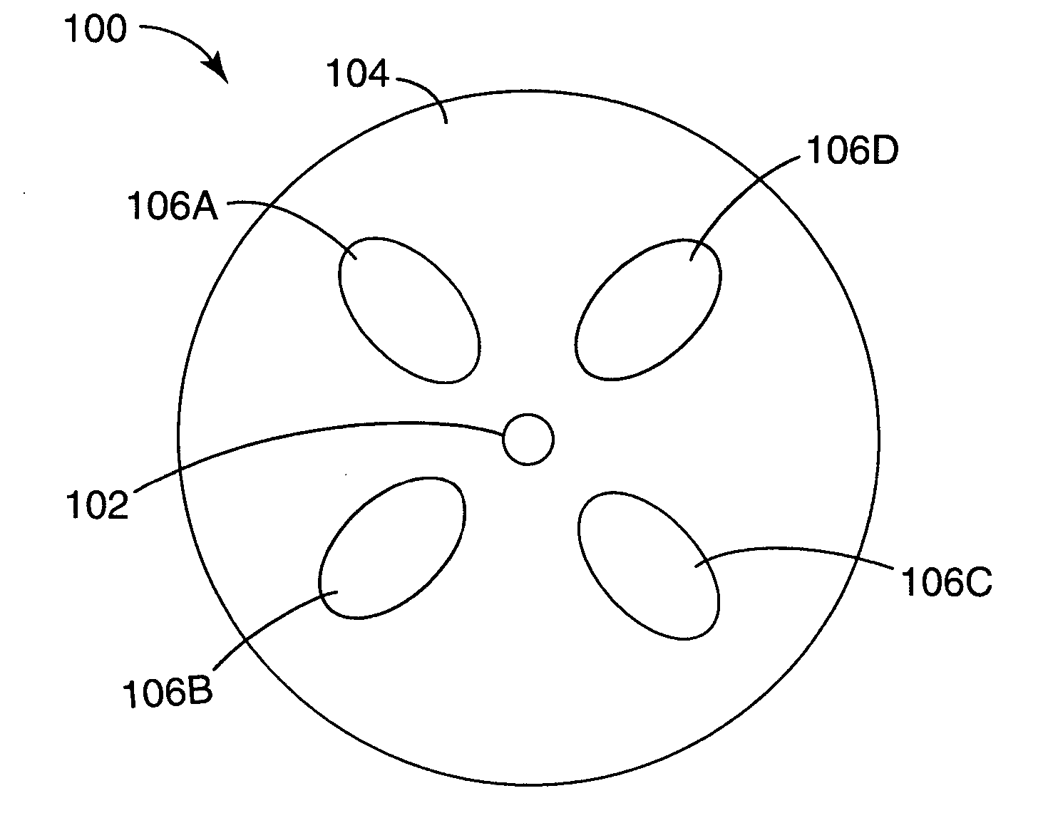
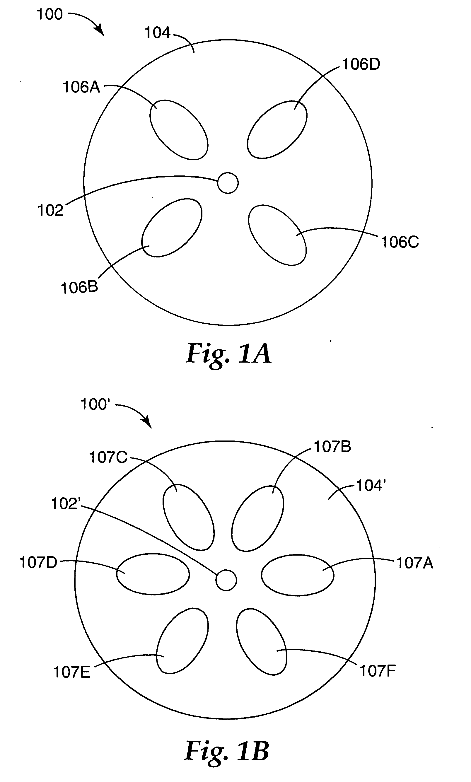
[0055] In a first example, a single mode preform was fabricated by conventional MCVD techniques. The finished diameter of the preform was 10.9 mm. Four slots of equal dimensions were ground into the preform by a conventional surface grinding machine and a conventional diamond impregnated grinding wheel. The grinding wheel thickness was 1.4 mm. During the grinding process, the preform was mechanically secured to the movable surface grinding table which was traversed continuously as the grinding wheel was slowly lowered to the specified slot depth (i.e., a conventional “plunge” grinding process). At the completion of the fabrication of one slot, the preform was rotated by 90 degrees and the process repreated to generate a second slot. This process was repeated until the desired four slots has been ground into the preform. The completed slots were about 1.4 mm wide and had a depth of about 4.5 mm.

[0056] The preform was chemically cleaned by conventional techniques. After cleaning, the...


PUM

PropertyMeasurementUnit
Diameteraaaaaaaaaa
Diameteraaaaaaaaaa
Lengthaaaaaaaaaa

Abstract

A hole-assisted fiber comprises a core region and a cladding region, where the cladding region includes multiple substantially elliptical holes spaced apart from each other to surround the core region. The holes are filled with one of a gas and a liquid to form a low refractive index portion of the cladding region.

Description

CROSS-REFERENCE TO RELATED APPLICATION [0001] This application is related to US patent application entitled “Method of Making a Hole Assisted Fiber Device and Fiber Preform”, Attorney Docket No. 60129US003, filed on even date herewith, the disclosure of which is incorporated by reference herein in its entirety. BACKGROUND OF THE INVENTION [0002] 1. Field of the Invention [0003] The present invention is directed to a hole-assisted optical fiber device. [0004] 2. Related Art [0005] Optical fibers are used to transport telecommunications data all over the world. Conventional optical fibers are glass-based filaments that include a core region surrounded concentrically by one or more cladding layers having appropriate indices of refraction to confine the transported light by total internal reflection. The outer cladding layer likewise is surrounded by an external medium, such as a buffer material. The optical fiber can be designed to support one guided mode of propagation (i.e., a single...

Claims


Application Information

Patent Timeline
IPC IPC(8): G02B6/032
CPCC03B37/0122C03B37/02781C03B2203/14C03B2203/42C03B2205/10C03C25/10G02B6/02357G02B6/02366G02B6/02371G02B6/02385G02B6/032
Inventor NELSON, BRIAN K.LYNCH, THOMAS M.DYRDA, JOSEPH A.ONSTOTT, JAMES R.VARNER, WAYNE F.
Owner 3M INNOVATIVE PROPERTIES CO
Why Eureka
Try Eureka