Erosion control barrier

a technology of erosion control and barrier, applied in excavations, construction, marine site engineering, etc., can solve the problems of reducing the ability of fiber rolls to direct fluid flow in a controlled manner, preventing the use of silt fences alone, and reducing the acceptance of applicants' candor, so as to reduce soil erosion and improve barriers. , the effect of disclosing the applicant's duty of candor

Inactive Publication Date: 2006-06-22
KRISTAR
View PDF26 Cites 39 Cited by
  • Summary
  • Abstract
  • Description
  • Claims
  • Application Information

AI Technical Summary

Benefits of technology

[0008] Yet another improved erosion control wattle is described in commonly owned U.S. Pat. No. 6,641,335, to Allard, naming the first named inventor of the present invention. The '335 patent shows a walled elongated core member having a first open end, a second end, an interior space and one or more openings in the wall communicating the interior space with the exterior of the core member. A fiber roll outer filter member surrounds the core member, which can be coupled with to one or two complimentary core members comprising tee connectors or elbow connectors. One advantage of the present invention is the ability to connect outlet pipes to tee or elbow connectors for directing fluid flow received by the core members to desired locations downstream of the core members.
[0009] The foregoing commonly owned patents reflect the state of the art devices of which the present inventors are aware. Reference to, and discussion of, these patents is intended to aid in discharging Applicant's acknowledged duty of candor in disclosing information that may be relevant to the examination of claims to the present invention. However, it is respectfully submitted that none of the above-indicated patents disclose, teach, suggest, show, or otherwise render obvious, either singly or when considered in combination, the invention described and claimed herein. Specifically, although each of the patents show improved barriers to intercept and divert water away from the barrier, there remains a problem with soil erosion in the area adjacent and around, underneath and downstream of the erosion rolls caused by water flowing to, over and underneath the rolls. BRIEF SUMMARY OF THE INVENTION
[0010] The erosion control barrier of the present invention represents yet another significant advance over the fiber roll wattles in the prior art. The present invention includes a walled elongate core member having a first open end, a second open end, an interior space, with one or more openings in the wall communicating the interior space with the exterior of the core member, and further including an outer, pervious filter member which surrounds the core member. In one embodiment, the outer filter member includes an apron which is affixed to the filter member along its length, and extends outwardly away from the core member. The apron is of a predetermined width, and includes means to secure the apron upstream of the elongate core member, so as to cover the ground adjacent said member, and direct fluid runoff and sediments to the elongate core member. Fluids passing through the pervious outer filter and through the openings in the wall of the elongate core member are carried by the core member to discharge points at the end of the core member.
[0011] The inventive apparatus (variously referred to herein as the inventive “erosion control roll” or the inventive “erosion control barrier”) may used in conjunction with a silt fence deployed in abutting relationship to the control roll. The stakes used in the deployment of the silt fence serve the secondary purpose of providing additional stabilization for the control roll. The silt fence can be formed integral to the control roll, in which event the silt fence extends from the downstream side of the filter member, in the opposite direction of the apron, and is provided with holes sized to receive securing ground stakes. In another embodiment the upstream apron may be covered with earth, to provide additional ballast for system fixation and stabilization.
[0012] As with the erosion control rolls of the above-indicated commonly owned patents, two or more core members may be connected together. Accordingly, one or both of the open ends can be fitted to couplers or connectors for connecting one core member to another. The couplers can comprise tee connectors or elbow connectors, which allows for the connection of outlet pipes to the tee or elbow connectors for re-directing fluid flow received by the core members to desired locations downstream of the core members.
[0013] It is therefore an object of the present invention to provide a new and improved erosion control barrier roll that provides runoff water diversion and filtering.

Problems solved by technology

Controlling soil erosion, such as erosion on slopes at construction sites, and particularly control of the sedimentation and debris carried in fluid flow on slopes is a continuing problem.
However, most regulatory agencies now discourage the use of silt fences alone due to the propensity for silt fences to collapse from high fluid flows and high winds.
However, fiber rolls are deficient in their ability to direct fluid flow in a controlled manner.
Moreover, numerous fiber rolls are generally required due to their inherent deficiencies in directing fluid flow as the flow proceeds down a slope.
Specifically, although each of the patents show improved barriers to intercept and divert water away from the barrier, there remains a problem with soil erosion in the area adjacent and around, underneath and downstream of the erosion rolls caused by water flowing to, over and underneath the rolls.

Method used


Image

  • Erosion control barrier
  • Erosion control barrier
  • Erosion control barrier

Examples


Embodiment Construction

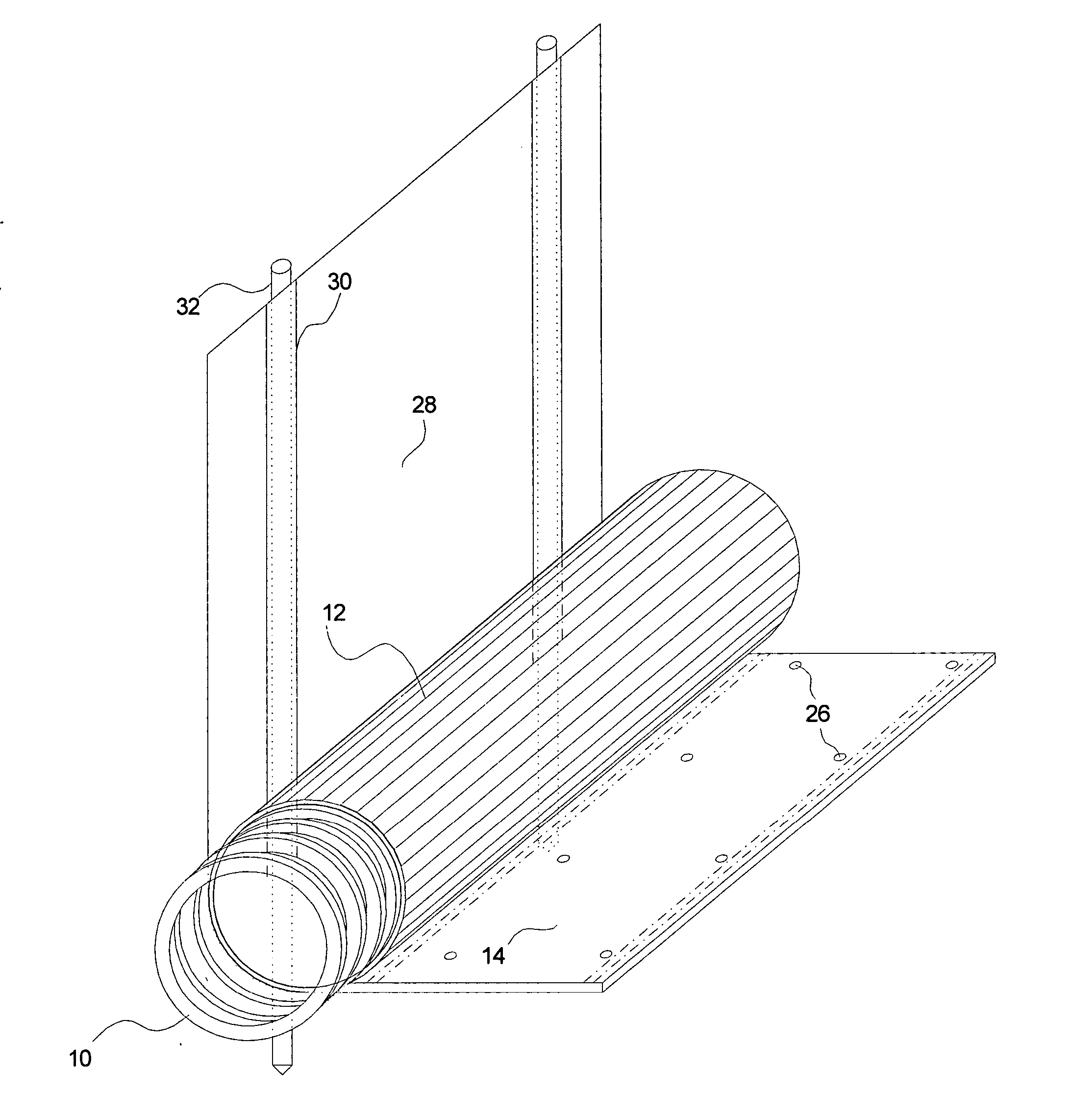
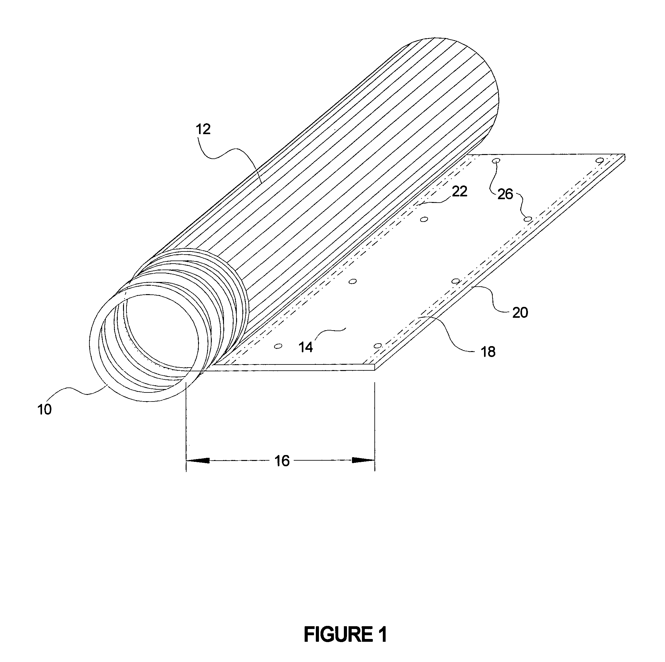
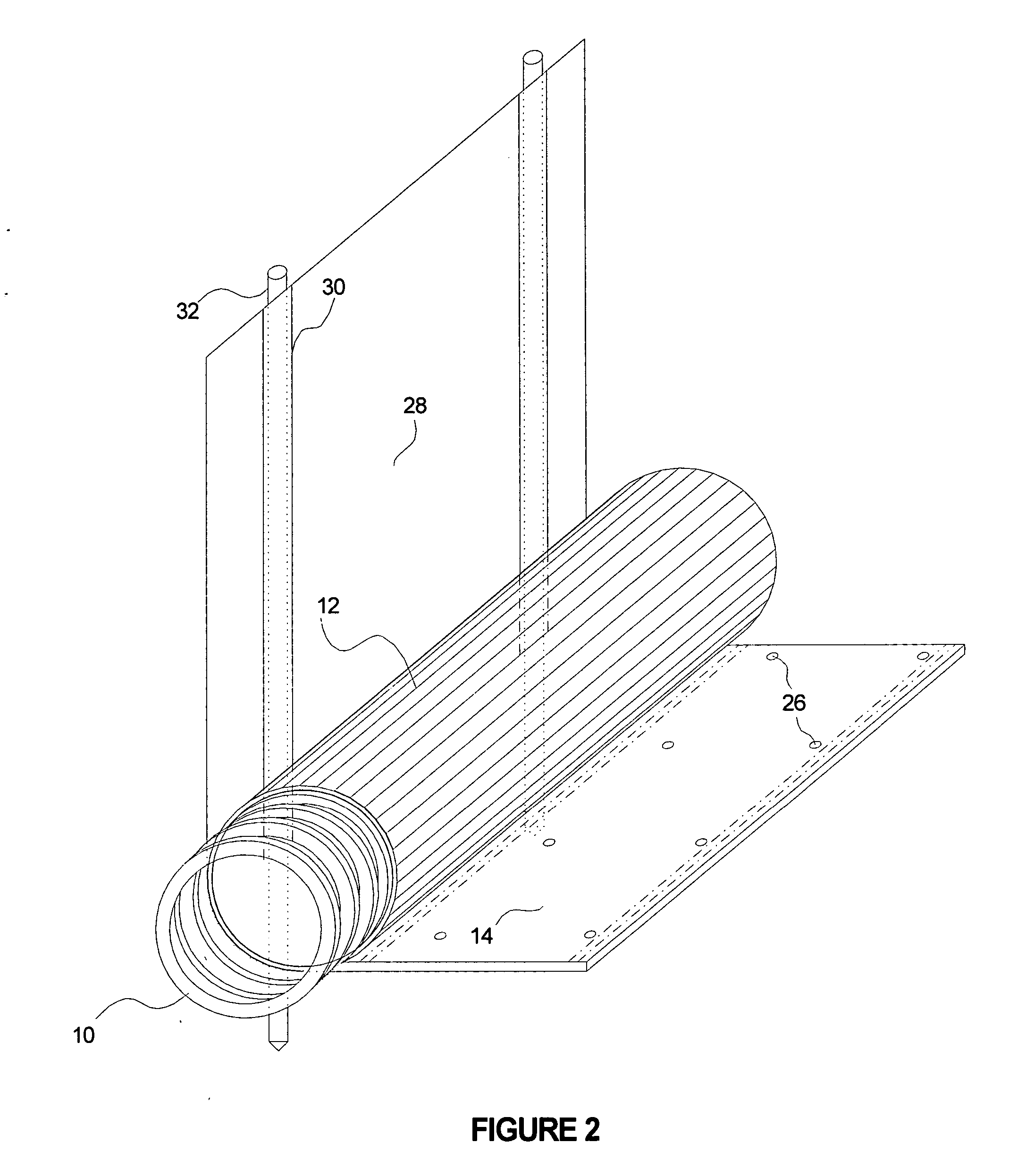
[0025] Referring to FIGS. 1 through 6, wherein like reference numerals refer to like components in the various views, there is illustrated therein a new and improved erosion control barrier. The erosion control barrier of the present invention is adapted for use in controlling sedimentation and debris flow, especially in connection with construction site and hillside runoff. In its most essential aspect, the apparatus includes a hollow core member covered with an outer filter member incorporating a longitudinal apron which serves several purposes: It provides means to secure the hollow core member to the ground; it directs fluid flow to the core member; and it covers the ground adjacent the core member to prevent soil erosion around and beneath the core member. The present invention is particularly useful in controlling erosion resulting from sedimentation and debris flow on slopes at construction sites and other areas where soil erosion poses environmental issues.

[0026] Referring ...


PUM


Abstract

An erosion control roll including an elongate core member defining an interior space, being open at both ends, and having openings along its length, a pervious filter member open at both ends and surrounding the elongate core member; and, an apron disposed on the upstream side of the pervious filter member, said apron running the length of said filter member, and extending a predetermined distance therefrom.

Description

CROSS REFERENCE TO RELATED APPLICATIONS [0001] The present application claims the benefit of the filing date of U.S. Provisional Patent Application Ser. No. 60 / 628,430, filed Nov. 16, 2004 (Nov. 16, 2004).STATEMENT REGARDING FEDERALLY SPONSORED RESEARCH OR DEVELOPMENT [0002] Not applicable. REFERENCE TO A MICROFICHE APPENDIX [0003] Not applicable. TECHNICAL FIELD [0004] The present invention relates generally to soils erosion control barriers, and more particularly to an erosion control barrier in which water runoff is diverted via the barrier to a remote point of discharge. BACKGROUND INFORMATION AND DISCUSSION OF RELATED ART [0005] Controlling soil erosion, such as erosion on slopes at construction sites, and particularly control of the sedimentation and debris carried in fluid flow on slopes is a continuing problem. Fiber rolls (also known as wattles) are the current industry standard for use in controlling erosion. Fiber rolls are typically made of fibrous materials such as stra...

Claims


Application Information

Patent Timeline
Patent Type & Authority Applications(United States)
IPC IPC(8): E02B11/00E02D17/20
CPCE02B3/04E02B11/005E02D17/20
Inventor ALLARD, DOUGLAS PAULMCDONALD, JONATHAN
Owner KRISTAR
Why Eureka
Try Eureka