
Air treatment apparatus and method

a technology of air treatment apparatus and air purification method, which is applied in the direction of lighting and heating apparatus, heating types, separation processes, etc., can solve the problems of lack of flexibility in the application of these conventional air cleaners, and achieve the effect of improving air purification efficiency and performance, and improving the air quality of the environmen

Inactive Publication Date: 2017-04-06
AKOS R&D
View PDF0 Cites 15 Cited by
  • Summary
  • Abstract
  • Description
  • Claims
  • Application Information

AI Technical Summary

Benefits of technology

The present invention offers an air treatment system that can improve air quality in different environments by using multiple air treatment units that can operate alone or in co-ordination with one another. The system is designed to be flexible and efficient, with enhanced performance and reduced material and consumable parts usage. The air treatment units can be operated in co-ordination with sensors or according to external command, minimizing the workload and reducing secondary pollutant generation. The invention allows for a wide range of applications, from small to large environments, and is suitable for different air purification requirements.

Problems solved by technology

The application of these conventional air cleaners actually lack of flexibility if they are to be shifted between areas of different sizes, and / or with pollutants of different sources and different levels, or if they are moved from a larger area to smaller area.

Method used


Image

  • Air treatment apparatus and method
  • Air treatment apparatus and method
  • Air treatment apparatus and method

Examples


Embodiment Construction

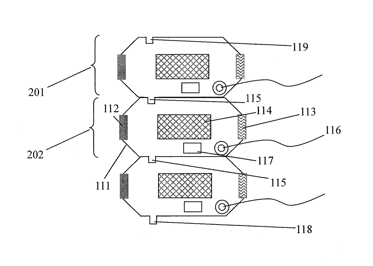
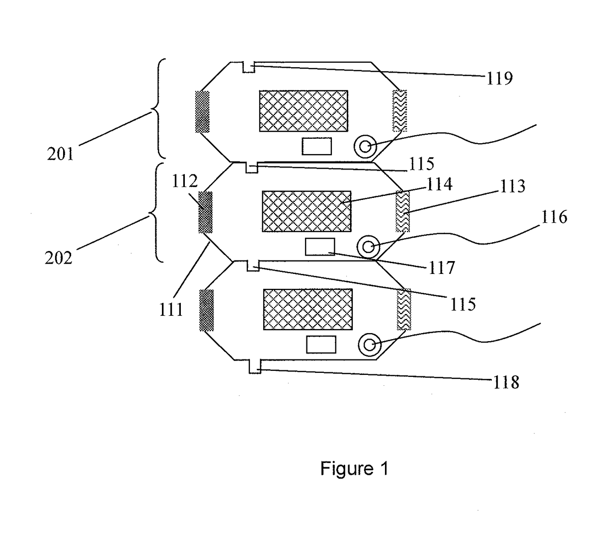
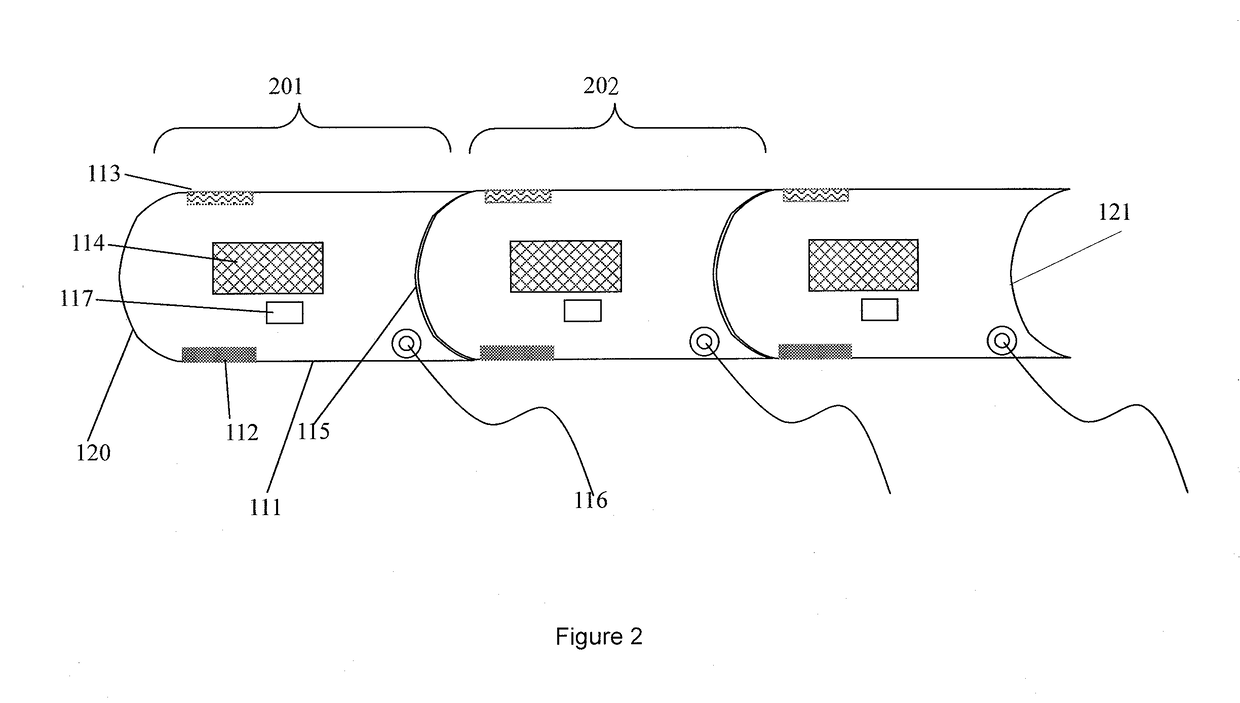
[0099]Refer to the FIG. 1; an air treatment system is built up by of three air treatment units 201, 202 and 203. Each air treatment unit 201, 202 and 203 comprises a casing 111, an air inlet 112, an air outlet 113, an air treatment device 114, connectors for connecting the electric sources 116, a central processing unit (CPU) 117 and a connecting component. The air treatment device 114 is equipped between the air inlet 112 and air outlet 113. The air inlet 112, air outlet 113, the connectors for connecting the electric sources 116 and the connecting component are located on the exterior of the casing 111. The air treatment device 114 and central processing unit 117 is equipped within the casing 111. If the manual mode is selected as the operating mode for these air treatments units, the operation setting inside the central processing unit is set manually. If the automatic mode is selected as the operating mode for these units, then the central processing units control the air treatm...


PUM

PropertyMeasurementUnit
Flexibilityaaaaaaaaaa
Total energyaaaaaaaaaa

Abstract

An air treatment apparatus and method are disclosed in the present invention, wherein, at least one air treatment unit is included. The unit comprises air inlet, air outlet, air treatment devices and connecting components. The air treatment device is located between the air inlet and the air outlet. The air treatment device comprises at least one of the following components: component for air purification and filtering, blow-through fan, draw-through fan, pump, component for heating, component for dehumidifying, component for humidifying, component for air-cooling. The air treatment unit can be used alone for improving the air quality of the environment. When more than one unit are connected together with the connecting components, the units are teamed up and work together, and an air treatment system is formed.

Description

[0001]This nonprovisional application is a continuation-in-part application of U.S. application Ser. No. 13 / 304,513, which was filed on Nov. 25, 2011, and which claims priority to Hong Kong Patent Application No. 11100409.2, which was filed in Hong Kong on Jan. 14, 2011, and which are both herein incorporated by reference.BACKGROUND OF THE INVENTION[0002]Field of the Invention[0003]This invention is related to the subject of the environmental protection. More specifically, it is related to an air treatment apparatus and method.[0004]Description of the Background Art[0005]Conventionally, air cleaners with filters of different variety and functions are employed for treating and purifying the air. They are also used for solving air quality problems generated by different sources of pollutants. These air cleaners are usually accompanied by filters of different types. In order to achieve more effective air purification, in a location with different pollutant levels, the airflow rate and ...

Claims


Application Information

Patent Timeline
IPC IPC(8): F24F1/02B01D46/00F24F6/00F24F13/20F24F13/28F24F11/00B01D46/46B01D46/42F24F8/167
CPCF24F1/02F24F2011/0038B01D46/0045B01D46/4263B01D46/0036B01D46/0023B01D46/4227F24F13/20F24F13/28F24F11/0012F24F11/0015F24F11/0017F24F6/00B01D2273/16B01D2279/51F24F2011/0064F24F2011/0068F24F2011/0042F24F2011/0049F24F2011/005B01D46/46F24F3/14F24F2221/36B01D53/32B01D53/75B01D53/82B01D53/885B01D2255/00B01D2257/104B01D2257/404B01D2257/502B01D2257/504B01D2257/708B01D2257/80B01D2257/91B01D2258/06B01D2259/804F24F11/30F24F2110/10F24F2110/20F24F2110/50F24F11/54Y02B30/70F24F11/80F24F11/526F24F11/63F24F11/74F24F8/22F24F8/80F24F8/167B01D46/62
Inventor LAW, SUI CHUNCHAN, YIU WAI
Owner AKOS R&D
Learn More