Integral heart rate monitoring garment

a heart rate monitor and integrated technology, applied in the field of heart rate monitors, can solve the problems of obstructing the use reducing the use efficiency of conventional heart rate monitors, so as to achieve the effect of reliable and effective us

Active Publication Date: 2006-06-22
POLAR ELECTRO
View PDF21 Cites 48 Cited by
  • Summary
  • Abstract
  • Description
  • Claims
  • Application Information

AI Technical Summary

Benefits of technology

[0008] It is an object of the present invention to provide an effective and reliable method and apparatus that integrate a transmitter, power source, and electrodes of a heart rate monitor with a wearable garment.
[0009] It is a further object of the present invention to provide a garment having an embedded heart rate transmitter, power source, and electrodes that can be worn, washed, and discarded as an integral unit.
[0010] It is still a further object of the present invention to provide a method and apparatus for reducing the quantity of equipment required during exercise or athletic activities.
[0011] It is another object of the present invention to provide a method and apparatus for making a heart rate monitor less restrictive, obtrusive, or likely to slip and more comfortable to wear.

Problems solved by technology

However, users are likely to find that the band 16 of the transmitter unit 10 is overly restrictive, obtrusive, and often slips during use since the band16 has limited contact with the body and needs to be tight to remain in the correct position.
The band 16 also requires a high degree of elasticity and the materials most conducive to this feature, such as plastic or rubber, typically trap moisture from perspiration, which causes conventional heart rate monitors to be uncomfortable when used on a regular basis.

Method used


Image

  • Integral heart rate monitoring garment
  • Integral heart rate monitoring garment
  • Integral heart rate monitoring garment

Examples


second embodiment

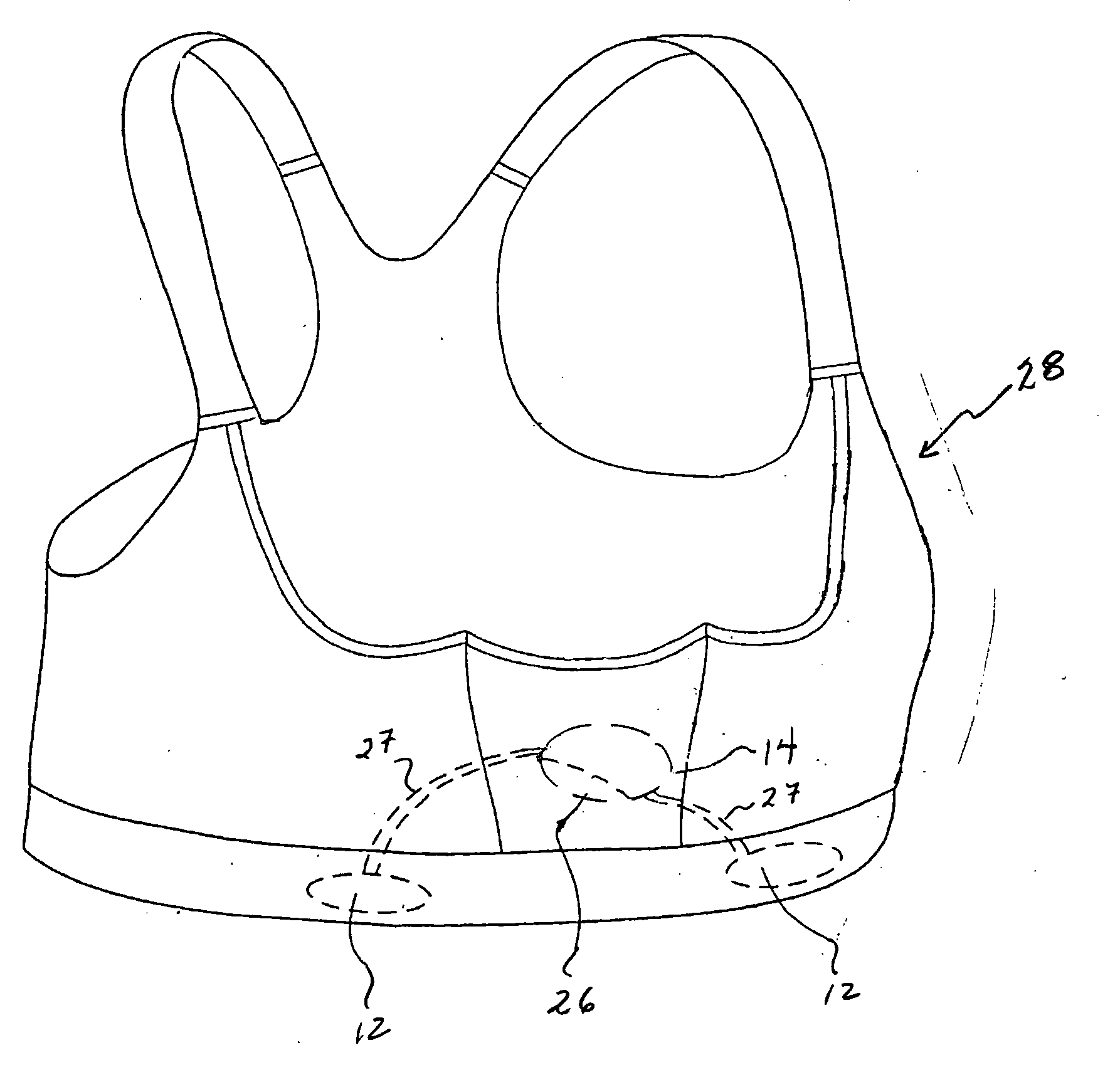
[0026]FIG. 3 shows a pictorial diagram of the heart rate monitoring garment 28, in which the electrodes 12, transmitter 14, and power source 26 are integrated with the garment 28 in the form of a sports brassiere. In this embodiment, the power source 26 has been collocated with the transmitter 14.

[0027]FIG. 4 shows a third embodiment of-the heart rate monitoring garment 30 accordance with the present invention, in which the power source 26 has been 5 positioned separately from the transmitter 14. The garment 30 is in the form of a halter-top. FIG. 5 is a pictorial diagram of a fourth embodiment of the heart rate monitoring garment 32, in which the power source 26 is preferably located within a pocket 34 of a tank top shirt.

fifth embodiment

[0028]FIG. 6 is a pictorial diagram of the heart rate monitoring garment 34 accordance with the present invention. The garment 34 is in the form of a tee shirt or athletic shirt, in which the transmitter 14 and electrodes 12 are located substantially collinearly.

[0029]FIG. 7 is a pictorial diagram of additional embodiments of the heart rate monitoring garment in accordance with the present invention. The garments shown in FIG. 7 are shown in the form of a wristband 36, armband 38, glove 40, leg warmer 42, ankle band 44, headband 46, sock 50, scarf 58, and earmuffs 60. It is anticipated that the heart rate monitoring garment of the present invention may assume forms and dimensions adapted for placement about various portions of the body while remaining within the scope of the present invention.

[0030] The power source 26 may include a rechargeable and / or replaceable battery. In these cases, access to the power source 26, which may be partially or completely removable, is preferably p...


PUM


Abstract

A garment adapted for monitoring a user's heart rate includes material, a transmitter, one or more electrodes, and a power source. The transmitter, electrodes, and power source are integrated with the material. The electrodes and power source are operatively coupled to the transmitter, and the electrodes are responsive to the user's heart rate. The garment is adapted for being worn, washed, and discarded with the electrodes, transmitter, and power source integrated therewith. A method of monitoring heart rate includes integrating a transmitter, electrodes, and power source with a garment, coupling the electrodes operatively to the transmitter, coupling the power source operatively to the transmitter, and adapting the garment for being worn, washed, and discarded with the transmitter, electrodes, and power source integrated therewith.

Description

BACKGROUND OF THE INVENTION [0001] 1. Field of the Invention [0002] The present invention relates generally to heart rate monitors, and more particularly relates to a heart rate monitoring garment adapted for being worn, washed, and discarded with an integral transmitter, power source, and electrodes. [0003] 2. Description of the Related Art [0004] Personal heart rate measurement devices or monitors non-invasively measure a user's heart rate and are commonly used by sports enthusiasts and athletes. As shown in FIG. 1, the heart rate monitor preferably includes a transmitter unit 10, which includes one or more electrodes 12 and a transmitter 14 attached to a belt 16 worn around the user's chest. The heart rate monitor also includes a receiver unit 18, which includes a microprocessor, user interface, and display 20 attached to a wristband 22. The transmitter unit 10 is in telemetric, inductive, and / or optical connection with the receiver unit 18. [0005] The user's heart rate is prefer...

Claims


Application Information

Patent Timeline
Patent Type & Authority Applications(United States)
IPC IPC(8): A61B5/04
CPCA61B5/0002A61B5/02438A61B5/0245A61B5/6804A61B5/6831
Inventor BIRNBAUM, BURTON H.SORVISTO, MIKA PETRI
Owner POLAR ELECTRO
Why Eureka
Try Eureka