
Modular controller apparatus and method

a controller and module technology, applied in the field of electronic apparatus modularization, can solve the problems of affecting the use of the controller during the installation period, and retaining drawbacks

Inactive Publication Date: 2006-06-22
CHICAGO PNEUMATIC TOOL
View PDF11 Cites 163 Cited by
  • Summary
  • Abstract
  • Description
  • Claims
  • Application Information

AI Technical Summary

Benefits of technology

[0007] The foregoing needs are met, to a great extent, by the present invention, wherein in one aspect an apparatus is provided that in some embodiments stacks a number of functional units, using a stacking-connector-based system bus for communication between units. Typical functional units can include displays, controls, and other operator interface elements, communication links to standar

Problems solved by technology

While the above configurations and others are known and accepted in the marketplace, they retain drawbacks.
Among these is the drawback that a controller receiving an upgrade is likely to be unavailable for use during an installation period.
Other drawbacks include the risk that an error in the upgrade process may cause protracted loss of use, and that a warranty or calibration certification may be voided by the work.
Another drawback is the likelihood that an upgrade, once installed in one unit, is seldom removed and installed in a different unit, so that upgrades are often effectively permanent.
This can lead to hesitation to acquire added capabilities for individual controllers, particularly if an added capability is needed in a particular controller for a short term.
The expense of having the upgrade performed is in some cases increased by the cost of shipping and the risk of hidden damage taking place during shipping.
Modularization by function within a controller is not assured, so that good components may be replaced along with faulty ones.
This can lead to increases in the cost of replaced components as well as in time and labor expended.

Method used


Image

  • Modular controller apparatus and method
  • Modular controller apparatus and method
  • Modular controller apparatus and method

Examples


Embodiment Construction

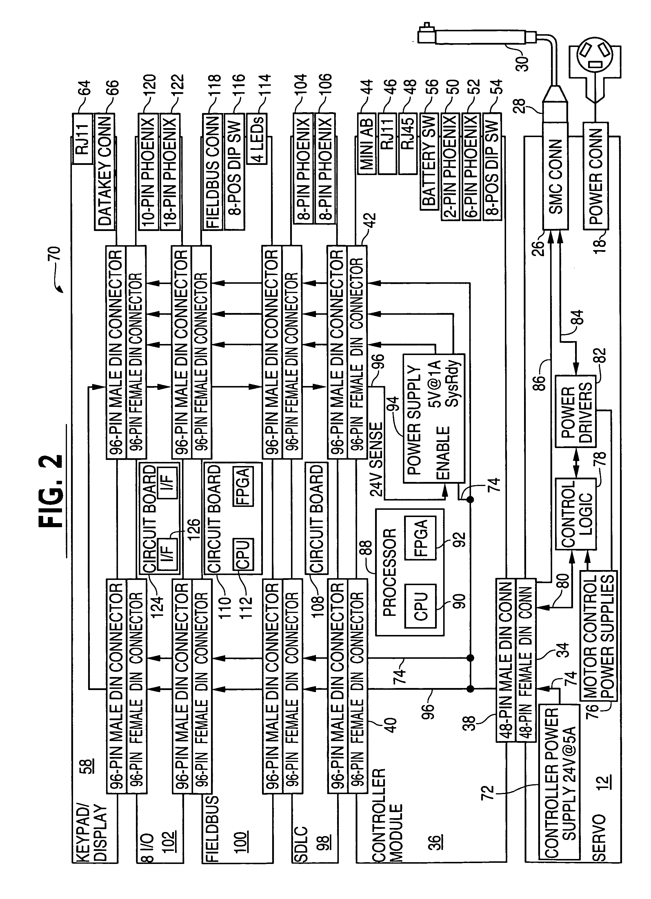
[0020] The invention will now be described with reference to the drawing figures, in which like reference numerals refer to like parts throughout. An embodiment in accordance with the present invention provides a modular servomotor controller electronics stack that permits functionality embodied in electronic devices housed within one or more stackable modules to be augmented by connecting additional modules. In other words, the controller can be given additional capabilities and features by adding modules. Some embodiments of the invention use a stacking connector system rather than a separate backplane to interconnect the functional modules.

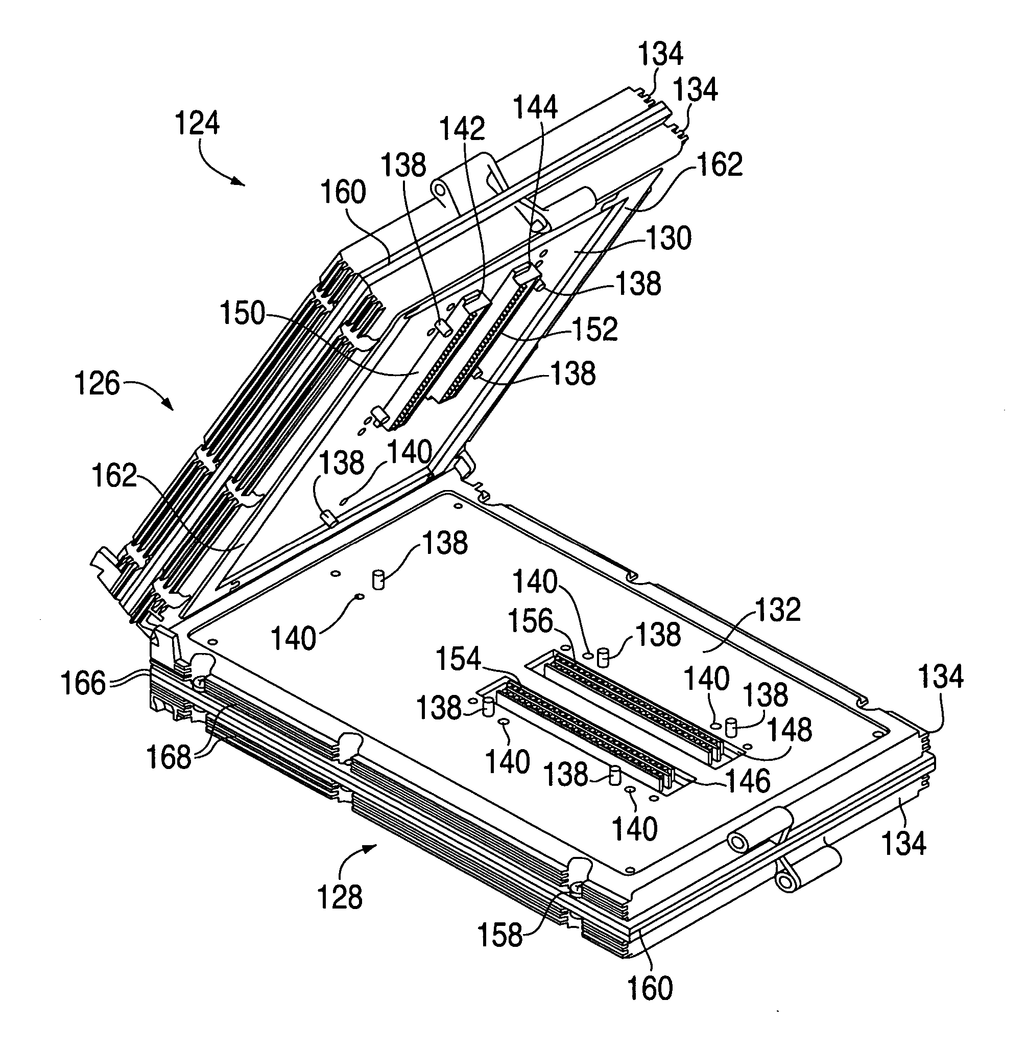
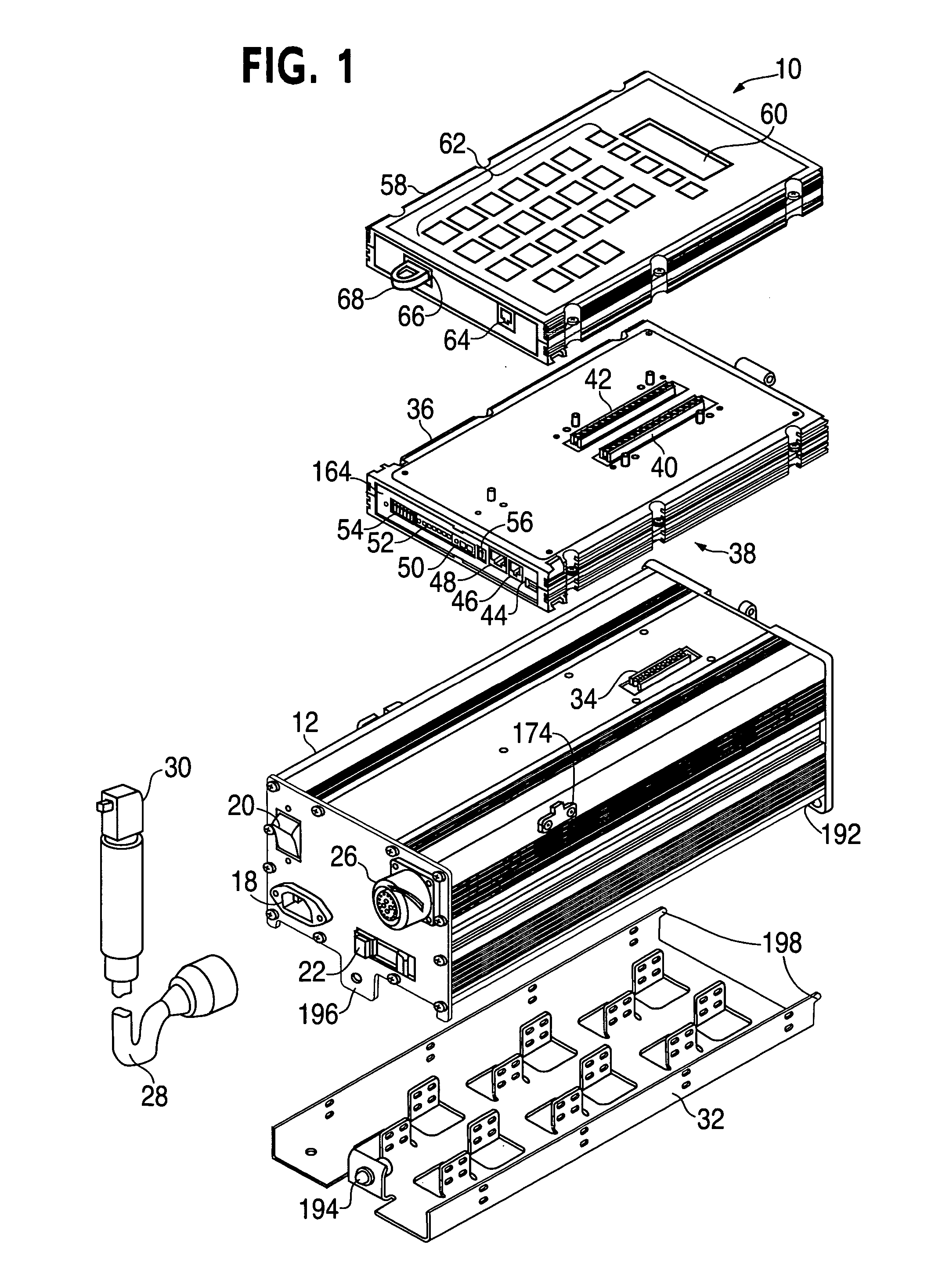
[0021]FIG. 1 is an exploded perspective view of a servomotor controller 10, assembled from representative set of modules, namely a User interface module 58, a Control Module 36, and a Servo module 12, provided with a mounting base 32.

[0022] The modules in this embodiment perform a series of functions associated with the features visible in th...


PUM


Abstract

A servomotor controller provides nut runner and other functions in a set of stackable modules. Extended-function modules can be added into and removed from the stack as needed. Destacking of closely spaced, wall-mounted controllers can be performed without demounting. Module assemblies are dripproof. Multiple sizes of nutrunner driver electronics and multiple keyboard and display options can be selected. A reprogrammable central processor can identify newly installed or removed features within a controller and reconfigure itself F accordingly. Stackable modules include Ethernet(®, multiple-bit I / O, and proprietary interfaces for many industries. The other modules communicate with the processor module via a backplaneless bus architecture. The central processor supports master / satellite group operation, whereby one controller unit can command multiple others, and whereby a higher-level system can command multiple controllers or multiple master / satellite controller groups.

Description

FIELD OF THE INVENTION [0001] The present invention relates generally to electronic apparatus modularization. More particularly, the present invention relates to stackable electronic modules for customizable servomotor controller configuration. BACKGROUND OF THE INVENTION [0002] Existing servomotor controller products are used for many purposes, including providing precisely controlled power to fastening tools known in the art as nutrunners. Servomotor controller products are presented in a variety of packaging configurations, as determined by such factors as operational requirements, marketing strategies, and cost considerations. For example, some servomotor controllers are offered by manufacturers as standalone entities with fixed envelope sizes and fixed lists of features. Other servomotor controller products are offered with multiple levels of capability; for these products, it is common to provide a fixed package size and a customizable list of features, with capabilities and o...

Claims


Application Information

Patent Timeline
IPC IPC(8): G06F13/38
CPCH05K5/0021H05K7/1432H05K7/1471H05K7/1481H05K7/14327
Inventor ROUVELIN, THIERRY R.BEESLEY, DARYLPIGGINS, LAWRENCE E.RITCHEY, MICHAEL L.
Owner CHICAGO PNEUMATIC TOOL
Learn More