Visual display of temperature differences for refrigerant charge indication

a technology of refrigerant charge and visual display, which is applied in the direction of temperature measurement in household appliances, domestic cooling apparatuses, instruments, etc., can solve the problems of increased power consumption, premature compressor failure, damage to motor and mechanical components,

Inactive Publication Date: 2006-06-29
CARRIER CORP
View PDF55 Cites 49 Cited by
  • Summary
  • Abstract
  • Description
  • Claims
  • Application Information

AI Technical Summary

Benefits of technology

[0006] Briefly, in accordance with one aspect of the invention, a simple and inexpensive refrigerant charge inventory indication method is provided using temperature measurements only.

Problems solved by technology

Improper charge level, either in deficit or in excess, can cause premature compressor failure.
An over-charge in the system results in compressor flooding, which, in turn, may be damaging to the motor and mechanical components.
Inadequate refrigerant charge can lead to increased power consumption, thus reducing system capacity and efficiency.
Low charge also causes an increase in refrigerant temperature entering the compressor, which may cause thermal over-load of the compressor.
Thermal over-load of the compressor can cause degradation of the motor winding insulation, thereby bringing about premature motor failure.
Consequently this is a tedious test procedure, and difficult to apply to air conditioners of different makers, or even for equipment of the same maker where different duct and piping configurations are used.
Thus, this charging procedure is also an empirical, time-consuming, and a trial-and-error process.

Method used


Image

  • Visual display of temperature differences for refrigerant charge indication
  • Visual display of temperature differences for refrigerant charge indication
  • Visual display of temperature differences for refrigerant charge indication

Examples


Embodiment Construction

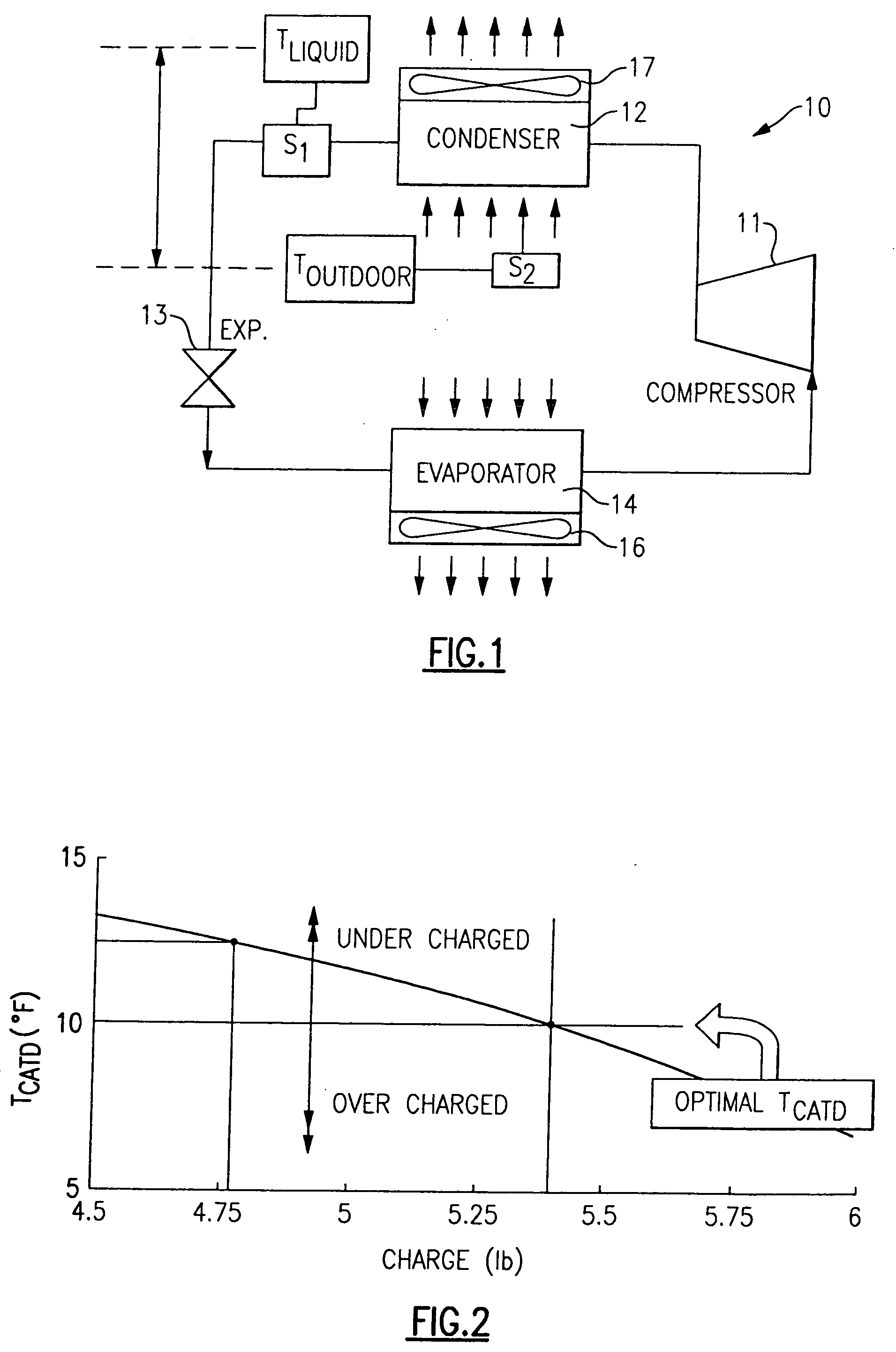
[0022] Referring now to FIG. 1, the invention is shown generally at 10 as incorporated into an air conditioning system having a compressor 11, a condenser 12, an expansion device 13 and an evaporator 14. In this regard, it should be recognized that the present invention is equally applicable for use with heat pump systems.

[0023] In operation, the refrigerant flowing through the evaporator 14 absorbs the heat in the indoor air being passed over the evaporator coil by the evaporator fan 16, with the cooled air then being circulated back into the indoor air to be cooled. After evaporation, the refrigerant vapor is pressurized in the compressor 11 and the resulting high pressure vapor is condensed into liquid refrigerant at the condenser 12, which rejects the heat in the refrigerant to the outdoor air being circulated over the condenser coil 12 by way of the condenser fan 17. The condensed refrigerant is then expanded by way of an expansion device 13, after which the saturated refriger...


PUM

PropertyMeasurementUnit
subcool temperatureaaaaaaaaaa
temperature TCTDaaaaaaaaaa

Abstract

The sufficiency of refrigerant charge in an air conditioning system is determined by a comparison of two sensed temperatures in the system, one being the liquid line temperature and the other being either the outdoor temperature or the condenser coil temperature. In one embodiment the two sensed temperatures are displayed on respective thermochromic strips which are so calibrated and juxtaposed as to provide a visual indication, by the relative positions of the two displayed sensed temperatures, as to whether the refrigerant charge is adequate. In another embodiment, the sensed liquid line temperature is displayed by way of a plurality of LEDs and the other temperature is displayed by way of a marker on a temperature scale. If the two displayed temperatures are aligned, then the refrigerant charge is optimized, and if they are not aligned, the system is undercharged or overcharged.

Description

BACKGROUND OF THE INVENTION [0001] This invention relates generally to air conditioning systems and, more particularly, to a method and apparatus for determining proper refrigerant charge in such systems. [0002] Maintaining proper refrigerant charge level is essential to the safe and efficient operation of an air conditioning system. Improper charge level, either in deficit or in excess, can cause premature compressor failure. An over-charge in the system results in compressor flooding, which, in turn, may be damaging to the motor and mechanical components. Inadequate refrigerant charge can lead to increased power consumption, thus reducing system capacity and efficiency. Low charge also causes an increase in refrigerant temperature entering the compressor, which may cause thermal over-load of the compressor. Thermal over-load of the compressor can cause degradation of the motor winding insulation, thereby bringing about premature motor failure. [0003] Charge adequacy has traditiona...

Claims


Application Information

Patent Timeline
Patent Type & Authority Applications(United States)
IPC IPC(8): F25B45/00G01K13/00
CPCF25B45/00F25B49/005F25B2700/04F25B2700/2106F25B2700/2116F25B2700/21163F25D2400/36G01K1/02G01K13/00G01K2201/00G01K2207/00
Inventor KANG, PENGJUFINN, ALAN M.GOPALNARAYANAN, SIVAKUMARLUO, DONGGALANTE, TIMOTHY P.
Owner CARRIER CORP
Why Eureka
Try Eureka