Chainsaw setting machine

a chainsaw and setting machine technology, applied in the direction of gear teeth, manufacturing tools, manufacturing apparatus, etc., can solve the problems of affecting the sharpening work of chainsaws, and difficult to continue the sharpening work in alignment with an accurate sharpening angle, so as to prevent the hand from wobbling, accurate sharpening angle and cutting edge angl

Inactive Publication Date: 2006-06-29
NISHIGAKI INDS
View PDF10 Cites 6 Cited by
  • Summary
  • Abstract
  • Description
  • Claims
  • Application Information

AI Technical Summary

Benefits of technology

[0013] Specifically, a grinding tool is not always oriented at an accurate sharpening angle by merely fitting and placing a guide body into and on a saw chain from above, because the guide body is designed with an allowance for the front-to-back width of the guide body relative to the left-to-right width of the saw chain so as to make it easy to fit the guide body into the saw chain from above. So, a design has been made that sets the two directions of the X-shape, as seen in plan view, to be directions in which the grinding tool is aligned with the sharpening angle, whereby an accurate sharpening angle and cutting edge angle can be obtained by fitting the guide body into the saw chain from above in an orientation of either direction of the X-shape in alignment with the orientation of a left or right cutter blade, and by pushing it forward. For this reason, wall faces, which are directed downward and are to be pressed against the guide bar (saw plate) for alignment with an accurate sharpening angle, are formed at a near side edge of the guide body corresponding to the X-shape as seen in plan view. By pushing the wall faces forward, the guide body is prevented from wobbling.
[0014] Note that in many kinds of chainsaws, a saw chain has a shape such that its central part slightly expands in an up-down direction. Thus, with an exposure portion, made of an opening or a curved portion to make it possible to watch a cutter blade to be sharpened and the grinding tool from above, being formed at a substantially central location in an upper surface of the guide body, it is not possible to prevent a cutter blade from wobbling or tilting due to its contact with the grinding tool rotating at a high speed. However, in the guide body of the sharpener of the present invention, a guide portion for pressing, from above, the cutter blade to be sharpened is provided on inside or side of the exposure portion so as to prevent the cutter blade from wobbling or tilting.
[0015] Further, this guide portion also has a big role to press, from above, a cutter blade to be sharpened so as to enable grinding which is aligned with a cutting edge angle of the cutter blade. In other words, the positional relationship between the guide portion and the grinding tool is defined to obtain an accurate cutting edge angle. Furthermore, this guide portion has a role, as well, to protect the face of a worker from metal power and sparks produced in the sharpening work.
[0016] The sharpener of the present invention has a structure as described above, so that it enables alignment with an accurate sharpening angle and cutting edge angle, with just an operation of fitting it from above into the saw chain in alignment with a central position of a cutter blade to be sharpened, and pushing it forward. So, even a person inexperienced in the sharpening can easily do an accurate sharpening in a short time. In this sharpener, an electric motor is used which uses a home power supply of 100V AC or uses a rechargeable battery. As an example of a preferable grinding tool, a diamond grindstone can be given which is formed of a round shaft having diamond particles fixed on an outer peripheral surface except a rear portion thereof.
[0017] The chainsaw sharpener according to the present invention enables sharpening in high efficiency, using a handy type electric motor. In particular, since the guide body has an X-shape to be able to fit into and in alignment with the sharpening angle of the left or right cutting edge of the saw chain, an accurate sharpening angle can be obtained with almost just one-touch operation of fitting the guide body into an upper part of the saw chain in alignment with a direction which is aligned with an orientation of a cutter blade to be sharpened, and pressing it against the guide bar of the chainsaw.
[0018] Furthermore, as a result of providing, on the upper plate face of the guide body, the guide portion to define an accurate cutting edge angle by pressing, from above, a cutter blade to be sharpened, it has become possible to prevent the cutter blade from wobbling or tilting and to do sharpening aligned with an accurate cutting edge angle, even when the grinding tool rotating at a high speed is brought into contact with the cutter blade to be sharpened. As a result of the above, it is possible even for a man or a woman, inexperienced in the sharpening, to do an accurate sharpening in a short time, making it unnecessary, as well, to patiently continue using a chainsaw which has become dull.

Problems solved by technology

It is understood that mere placing of the cover plate or the angle adjustment plate on the saw chain is not sufficient to stabilize the posture of the grinder or the sharpener, and that a hand is likely to wobble during the sharpening work, and thus that it is not easy to continue the sharpening work in alignment with an accurate sharpening angle or cutting edge angle.
An attempt to align with a correct sharpening angle or cutting edge angle is likely to tire the hand gradually and thereby produce sharpening with a bad finish.

Method used


Image

  • Chainsaw setting machine
  • Chainsaw setting machine
  • Chainsaw setting machine

Examples


Embodiment Construction

[0031] A best mode for carrying out the present invention will be described hereinafter with reference to the drawings.

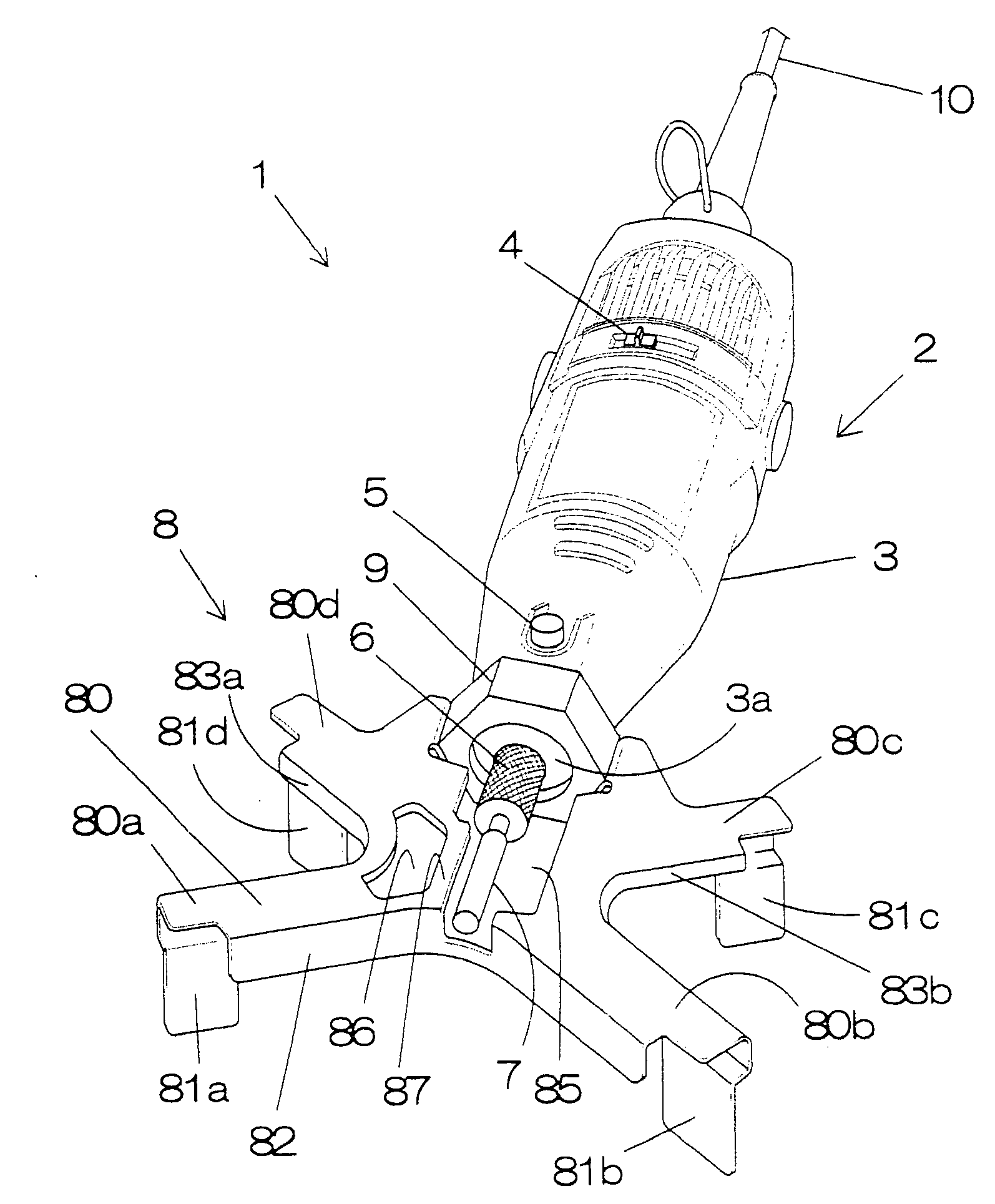
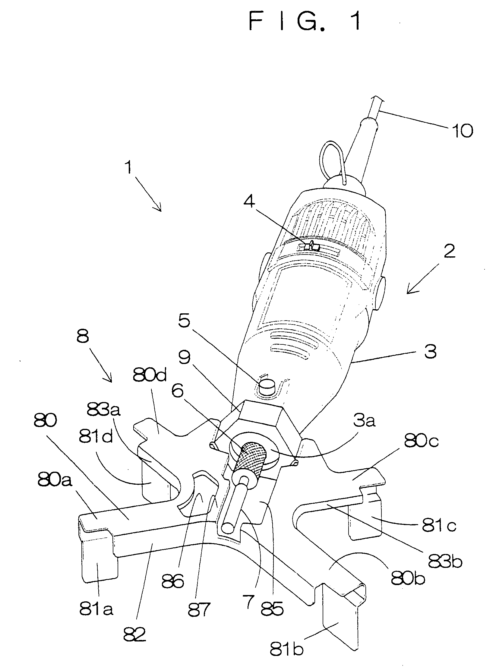
[0032]FIG. 1 to FIG. 6 show a chainsaw sharpener according to an embodiment of the present invention. As shown in these drawings, a chainsaw sharpener 1 according to the embodiment of the present invention is formed in a manner that a guide body 8 is detachably mounted on and forward of a sharpener body 2 which has a round shaft-shaped grinding tool 7 mounted on a front end portion of a drive shaft of an electric motor 3.

[0033] The electric motor 3 is a handy type to be driven by a DC power supply or an AC power supply, which is taken from outside, or a rechargeable battery. FIG. 1 and FIG. 2 show an electric motor 3 to be driven by a home power supply. The electric motor 3 used has a body case with a power supply switch 4 to be slided to turn the power supply on and off, and with a brake button 5 to brake the rotation of the drive shaft, and further has a power s...


PUM


Abstract

In a chainsaw sharpener, a round shaft-shaped grinding tool (7) is attached to an end of a drive shaft of a handy type electric motor (3). Mounted on and forward of the electric motor of a sharpener body (2) via a mounting portion (9) is a guide body (8) having, formed therein, an upper plate face (80) and wall faces (81a to 81e) which have a substantial X-shape as seen in plan view, extending in two directions, and which are fit into and along an upper part of the saw chain in alignment with a sharpening angle of either a left or right cutter blade (31, 32) of a saw chain (30). Formed at a substantially central surface of the guide body (8) is an exposure portion made of openings (85, 86) which make it possible to watch, from above, the grinding tool (7) and a cutting edge of a cutter blade to be sharpened. Provided on inside or side of the exposure portion is a guide portion (87) for pressing, from above, the cutter blade to be sharpened so as to prevent the cutter blade from wobbling or tilting, and further to define an accurate cutting edge angle. According to this structure, with just an operation of placing the guide body along a position aligned with the sharpening angle of either the left or right cutter blade, and pushing it forward, it is possible to stabilize the posture of the cutter blade, thereby enabling sharpening aligned with an accurate sharpening angle and cutting edge angle, and to efficiently do the sharpening work.

Description

TECHNICAL FIELD [0001] The present invention relates to a chainsaw sharpener in which a round shaft-shaped grinding tool attached to an end of an electric motor is rotated to grind and thereby sharpen, at a side portion thereof, a cutting edge of a cutter blade of a saw chain provided on a chainsaw. It particularly relates to a chainsaw sharpener which enables sharpening, aligned with an accurate sharpening angle and cutting edge angle, easily in a short time with just a simple operation of fitting it from above into the saw chain in an orientation corresponding to either a left or right cutter blade, and pushing it forward. BACKGROUND ART [0002] Conventionally, a chainsaw has attached thereto a saw chain having an endless shape. The saw chain has left-facing cutter blades and right-facing cutter blades provided at constant intervals and in directions opposite to each other. Upper blades of these blades have a sharpening angle which is, for example, tilted backward at 30°. Cutting e...

Claims


Application Information

Patent Timeline
Patent Type & Authority Applications(United States)
IPC IPC(8): B23D63/16
CPCB23D63/162
Inventor NISHIGAKI, TAKANOBU
Owner NISHIGAKI INDS
Why Eureka
Try Eureka