Single-wedge wrenches

a single-wedge, wrench technology, applied in the field of hand tools, can solve the problems of reducing efficiency, affecting the use of tools, and the edge of the object is likely to be damaged, and achieve the effect of simple manufacturing process and increased torque of rotation

Inactive Publication Date: 2006-06-29
LU HONG
View PDF7 Cites 14 Cited by
  • Summary
  • Abstract
  • Description
  • Claims
  • Application Information

AI Technical Summary

Benefits of technology

[0007] To overcome the shortcomings in the prior art as described above, the present invention provides a single-wedge wrench, which does not need to frequently adjust the position of disengaging and reengaging an object such as a nut, can apply a relatively larger torque of rotation to the object, and is of a simple manufacturing process.

Problems solved by technology

Such conventional wrenches have the following disadvantages in gripping and rotating an object such as a pipe or a nut: (1) The gripping surfaces of the jaw are liable to slip along a surface of the object; (2) When the wrench works in a limited space, the wrench must be adjusted to reengage the object frequently, which decreases the efficiency; and (3) The edge of the object is likely to be damaged by a force directly applied thereto by the wrench.
However, such a wrench has some drawbacks.
(1) It cannot be used for a small size object, because when the front ends of the two gripping surfaces, each configured in an arc shape, contact each other, there is a gap between the rear ends thereof.
(2) Since the wedge is directly fixed in the sliding hole by a locating pin, the pin is easily damaged by a force the object exerts on the wedge during the operation.
(4) The production of the wrench requires a complex process.

Method used


Image

  • Single-wedge wrenches
  • Single-wedge wrenches
  • Single-wedge wrenches

Examples


Embodiment Construction

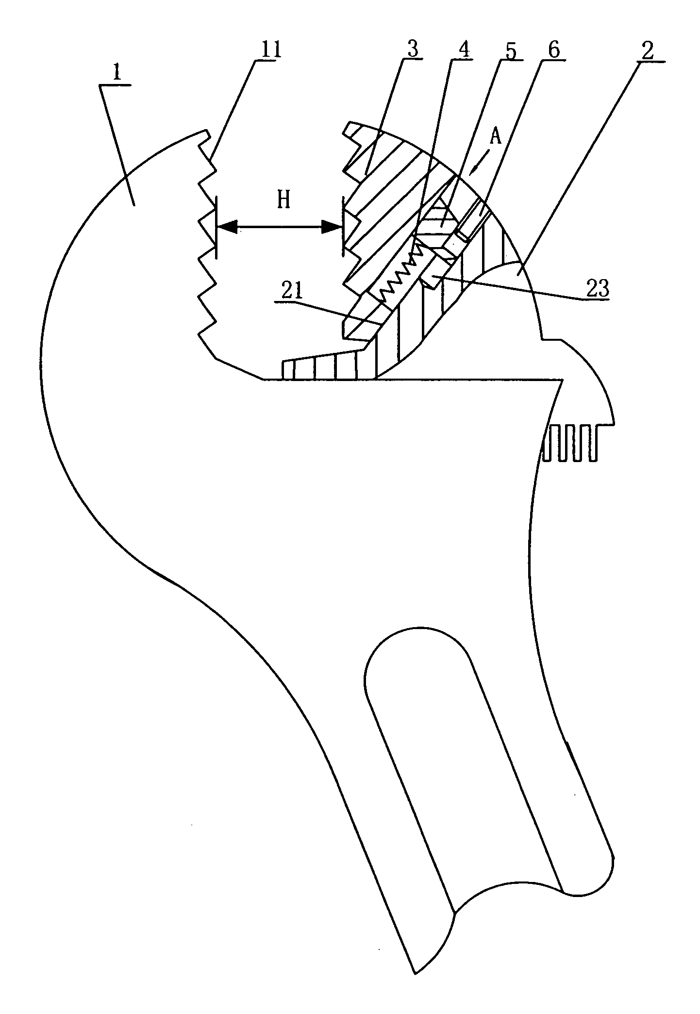
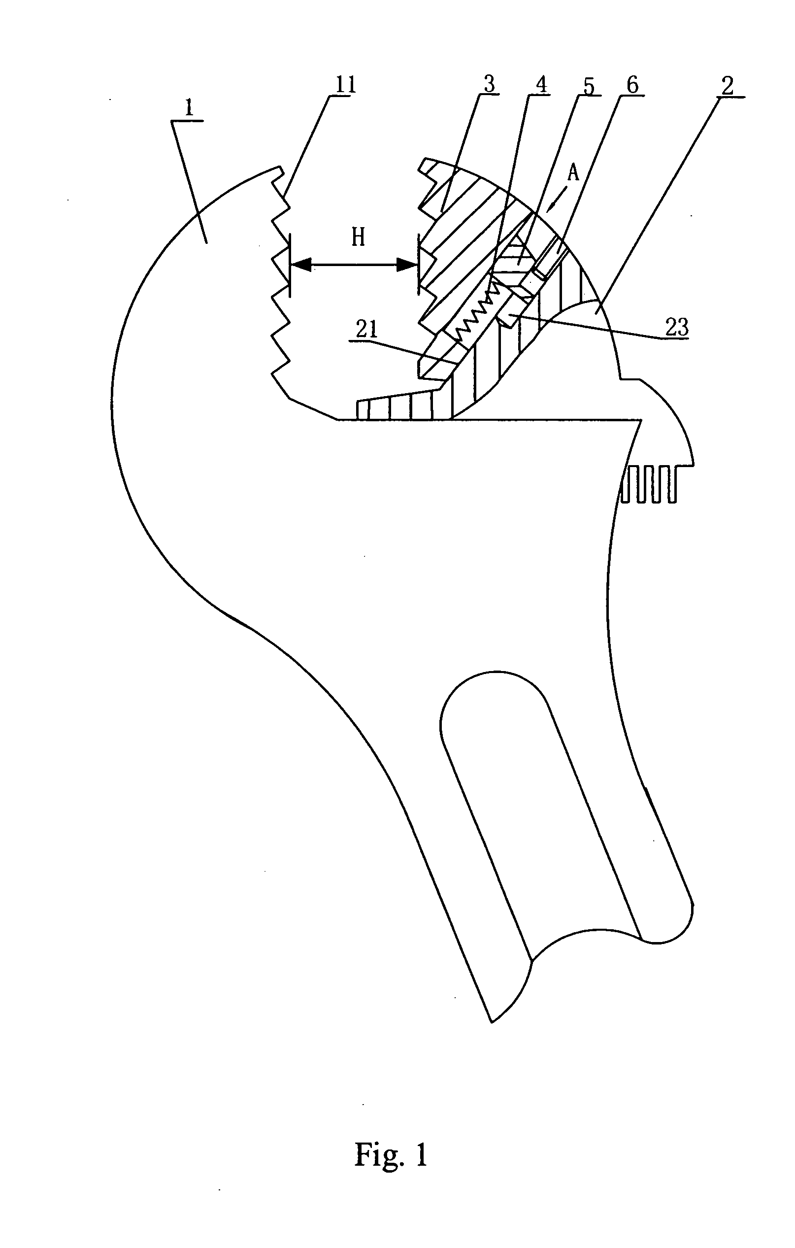
[0033] With reference to the drawings, the preferred embodiments of the present invention will be further described as follows.

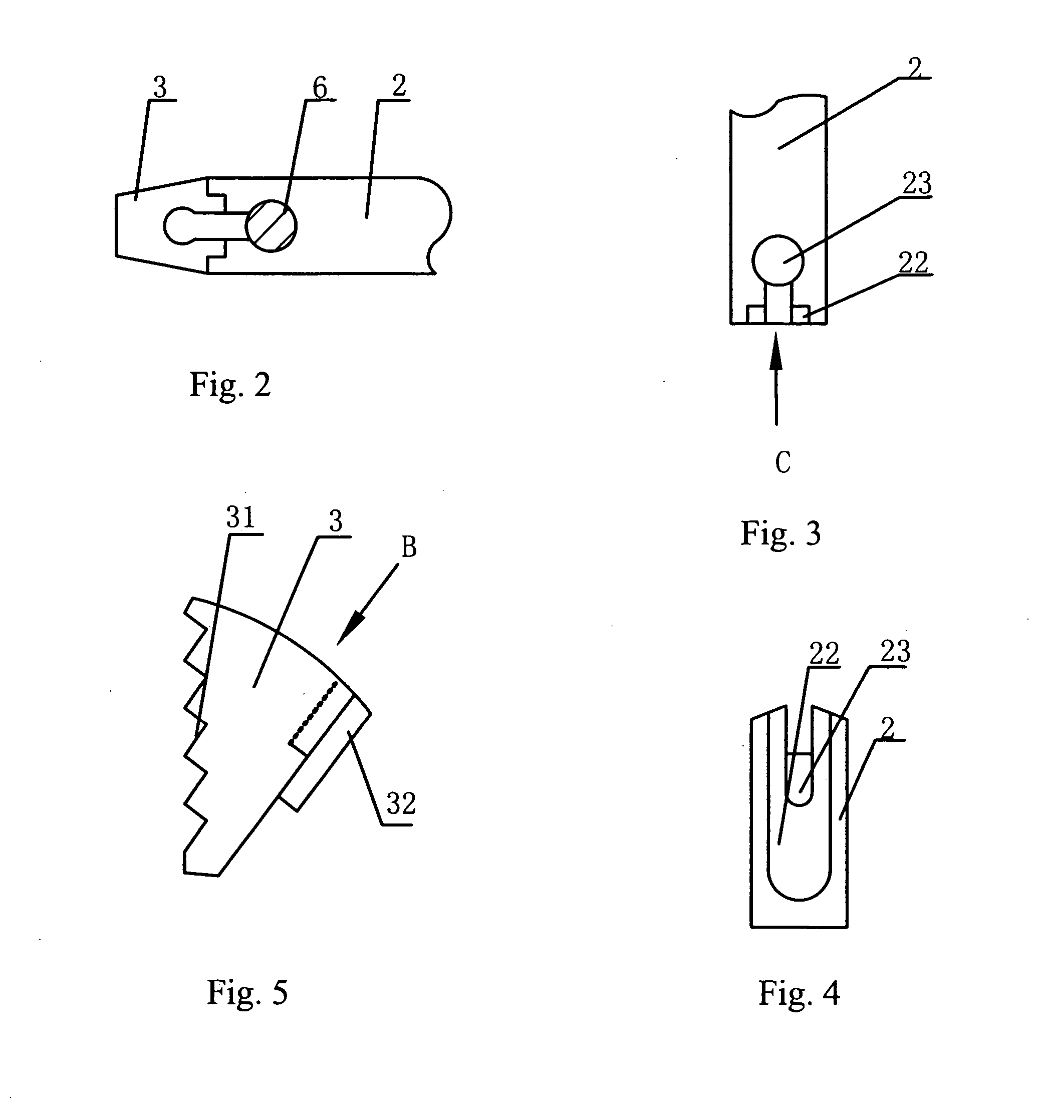
[0034] FIGS. 1 to 8 show a wrench according to a first preferred embodiment of the present invention. As shown in FIG. 1, a head portion of the wrench of the preferred embodiment has a stationary jaw 1 and an adjustable jaw 2. A zigzag gripping surface 11 is provided at the stationary jaw 1. Referring to FIG. 3 and FIG. 4 also, a guiding slot 22 and a blind hole 23 communicated with the guiding slot 22 are provided at an inner surface 21 of the adjustable jaw 2 opposite to the stationary jaw 1.

[0035] As shown in FIG. 2, FIG. 5 and FIG. 6, the wrench of the first preferred embodiment of the present invention further comprises a wedge 3, which is mounted on the adjustable jaw 2, provides a zigzag gripping surface 31. A guiding rail 32 is configured at a surface of the wedge 3, which matches the inner surface 21 of the adjustable jaw 2. The guiding rail 32 ma...


PUM


Abstract

Disclosed is a single wedge wrench including two jaws, one of which has a zigzag gripping surface. The wrench further includes a wedge having a zigzag gripping surface. The wedge is mounted on an inner surface of the other one of the two jaws by means of a joint member, being slidable along the inner surface. The wrench disclosed can be used for bolts or nuts with various types and sizes, and an operation can be performed as long as a handle of the wrench is returned. The wrench can be manufactured with a simple process in a production line.

Description

BACKGROUND OF THE INVENTION [0001] 1. Field of the Invention [0002] The present invention relates to a hand tool, and more particularly to a wrench having a jaw with a wedge. [0003] 2. Description of the Prior Art [0004] There have been two kinds of wrenches in the art. One is an adjustable wrench and the other is a solid wrench. The wrench in the art comprises a handle and a jaw. Gripping surfaces of the jaw are typically flat and face each other in parallel. Such conventional wrenches have the following disadvantages in gripping and rotating an object such as a pipe or a nut: (1) The gripping surfaces of the jaw are liable to slip along a surface of the object; (2) When the wrench works in a limited space, the wrench must be adjusted to reengage the object frequently, which decreases the efficiency; and (3) The edge of the object is likely to be damaged by a force directly applied thereto by the wrench. [0005] In order to solve the problems of the gripping force of the conventiona...

Claims


Application Information

Patent Timeline
Patent Type & Authority Applications(United States)
IPC IPC(8): B25B13/16B25B13/12B25B13/46
CPCB25B13/46B25B13/12
Inventor LU, HONG
Owner LU HONG
Why Eureka
Try Eureka