Double break disconnect switch
- Summary
- Abstract
- Description
- Claims
- Application Information
AI Technical Summary
Benefits of technology
Problems solved by technology
Method used
Image
Examples
Embodiment Construction
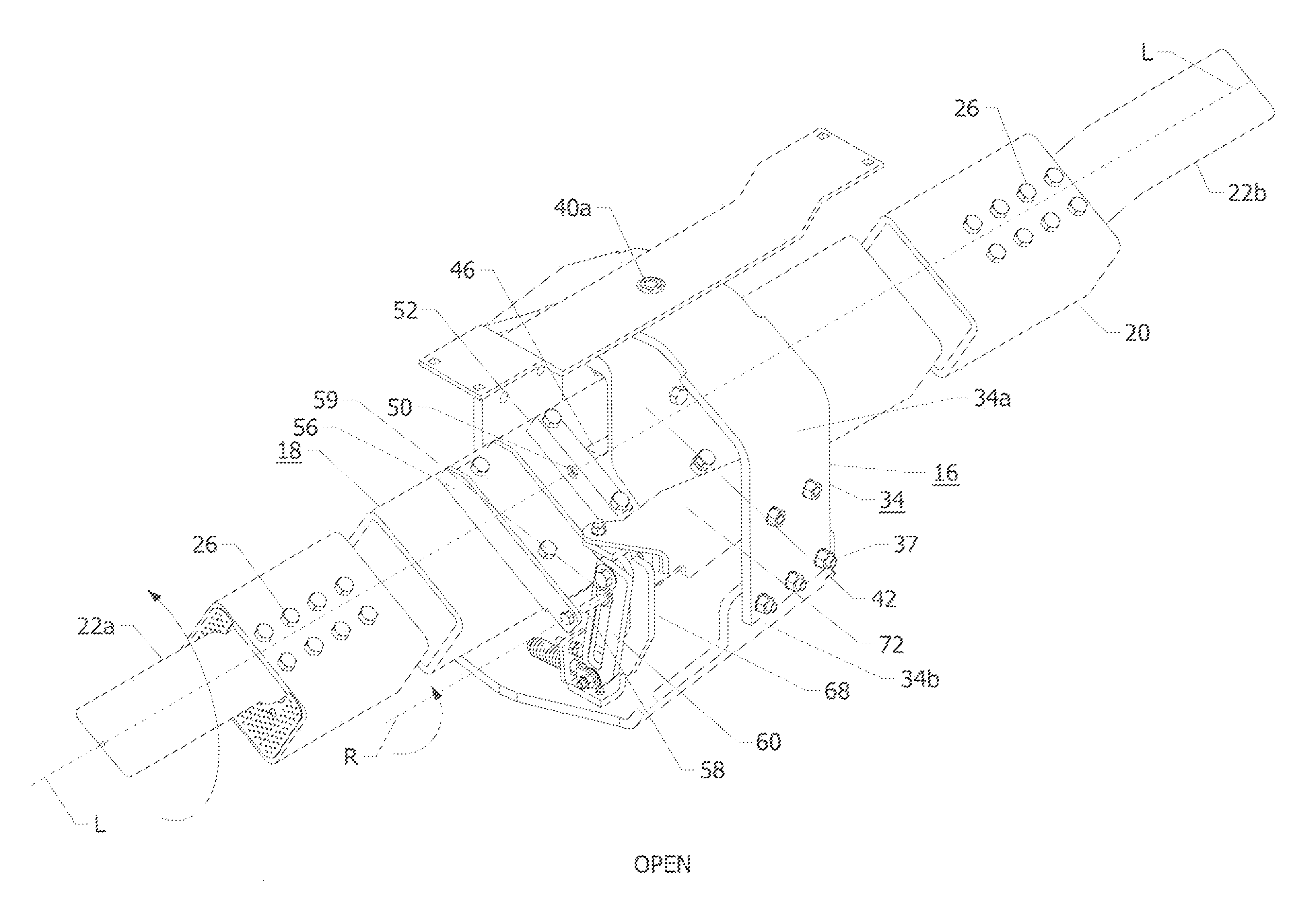
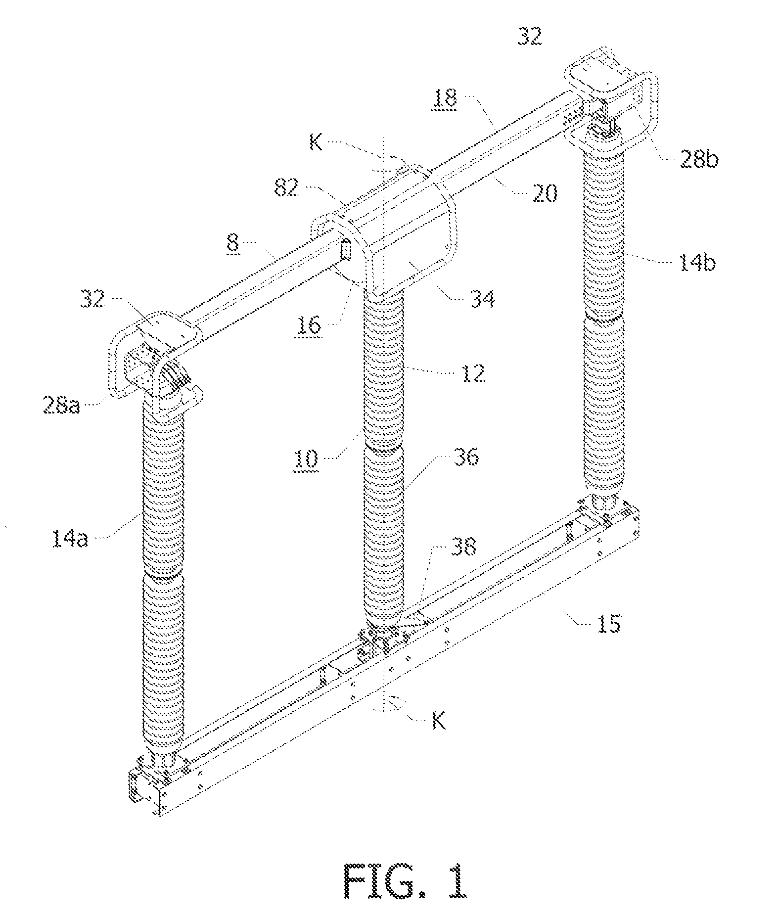
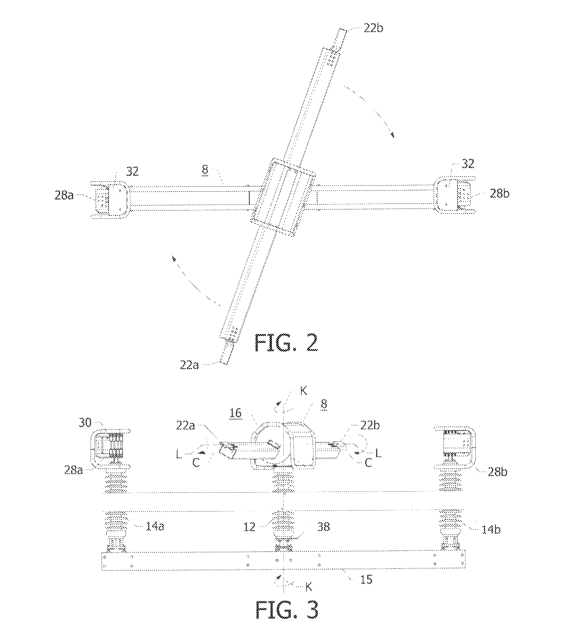
[0029]With reference to FIGS. 1-3, a double break disconnect switch 8 for high voltage applications is shown comprising a drive arrangement 10 which includes a rotatable support assembly 36 including center rotatable insulator 12 and fixed insulators 14a, 14b and a lever 38 mounted to a base member 15. The supporting structure which includes the center rotatable insulator 12 and the fixed insulators 14a, 14b may be arranged as shown in FIG. 1 or may be in a split V configuration, not shown, for example. A bearing arrangement 16 is mounted on the drive arrangement 10 on the top of the rotatable insulators 12. The drive arrangement 10 is in relative movement relationship with respect to the bearing arrangement 16 via the lever 38. A switch blade assembly 18 includes a tubular switch blade 20 which may have a rectangular shape and be made of aluminum, for example. In FIGS. 4 and 5, the switch blade 20 has contact terminals 22a, 22b, i.e., blade tips attached to its ends. The switch bla...
PUM
 Abstract
Description
Claims
Application Information
 - R&D
- Intellectual Property
- Life Sciences
- Materials
- Tech Scout
- Unparalleled Data Quality
- Higher Quality Content
- 60% Fewer Hallucinations
Browse by: Latest US Patents, China's latest patents, Technical Efficacy Thesaurus, Application Domain, Technology Topic, Popular Technical Reports.
© 2025 PatSnap. All rights reserved.Legal|Privacy policy|Modern Slavery Act Transparency Statement|Sitemap|About US| Contact US: help@patsnap.com


