
Transmission structure for an electrically operated bicycle

a transmission structure and electric bicycle technology, applied in the direction of bicycles, interlocking clutches, gearing, etc., can solve the problems of inability to assist the electric mechanism, the pedal mechanism is relatively inconvenient to use, and the prior art structure is more complex, etc., to achieve the effect of improving the structure of the transmission structure, simple structure and large rotating torqu

Inactive Publication Date: 2008-05-08
PERNG TE YU
View PDF10 Cites 20 Cited by
  • Summary
  • Abstract
  • Description
  • Claims
  • Application Information

AI Technical Summary

Benefits of technology

[0006]A primary objective of the present invention is to provide an improved structure of a transmission structure for an electrically operated bicycle that has a simple structure, large rotating torque, wearproof, and is able to achieve automatic switching between electrical operation and pedal operation.
[0007]Another objective of the present invention is to provide the improved structure of a transmission structure for an electrically operated bicycle with a driving chain wheel which can be a multiple sprocket chain wheel, thereby achieving a variable speed electrically operated bicycle.
[0008]Yet another objective of the present invention is to provide the improved structure of a transmission structure for an electrically operated bicycle with functionality to coordinate with a forward and reverse switcher configuration to achieve an electrically operated bicycle that has functionality to move forward or backward.
[0010]According to the aforementioned structural assembly, when rotational speed of the rotating shaft of the electric mechanism is relatively fast, then the clutch can be used to actuate the driving chain wheel, and when rotational speed of the rotating shaft of the electric mechanism is relatively slow or is not rotating, then both feet can be used to step on the pedal cranks to drive and rotate the driving chain wheel through the unilateral bearing, thereby achieving a dual purpose electrical operated and pedal operated transmission structure.

Problems solved by technology

Hence, prior art structures are more complex, and relatively inconvenient in use.
Moreover, because of the separate disposition of the electric mechanism and pedal mechanism in prior art structures, thus, the electric mechanism portion is unable to function in coordination with a variable speed multiple sprocket chain wheel, and only enables providing the pedal mechanism with functionality of multistage speed change (as found on variable speed bicycles of prior art); Furthermore, when prior art structures meet an inclined roadway and there is insufficient electric drive torque, the pedal mechanism is unable to assist the electric mechanism to drive the bicycle forward.

Method used


Image

  • Transmission structure for an electrically operated bicycle
  • Transmission structure for an electrically operated bicycle
  • Transmission structure for an electrically operated bicycle

Examples


Embodiment Construction

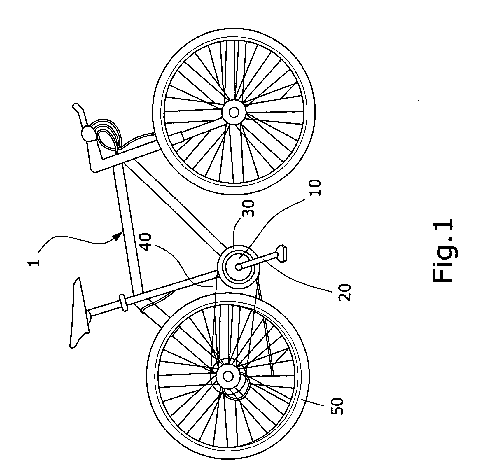
[0018]Referring to FIG. 1, which shows a schematic view of the entire body of an electrically operated bicycle, wherein an electrically operated bicycle 1 is provided with an electric mechanism 10 coaxially installed at a pedal shaft position of a traditional pedal mechanism 20, thereby enabling the pedal mechanism 20 or / and the electric mechanism 10 to be used to drive and rotate a driving chain wheel 30, which then drives and rotates a rear wheel 50 by means of a chain 40, thereby driving the electrically operated bicycle 1 forward.

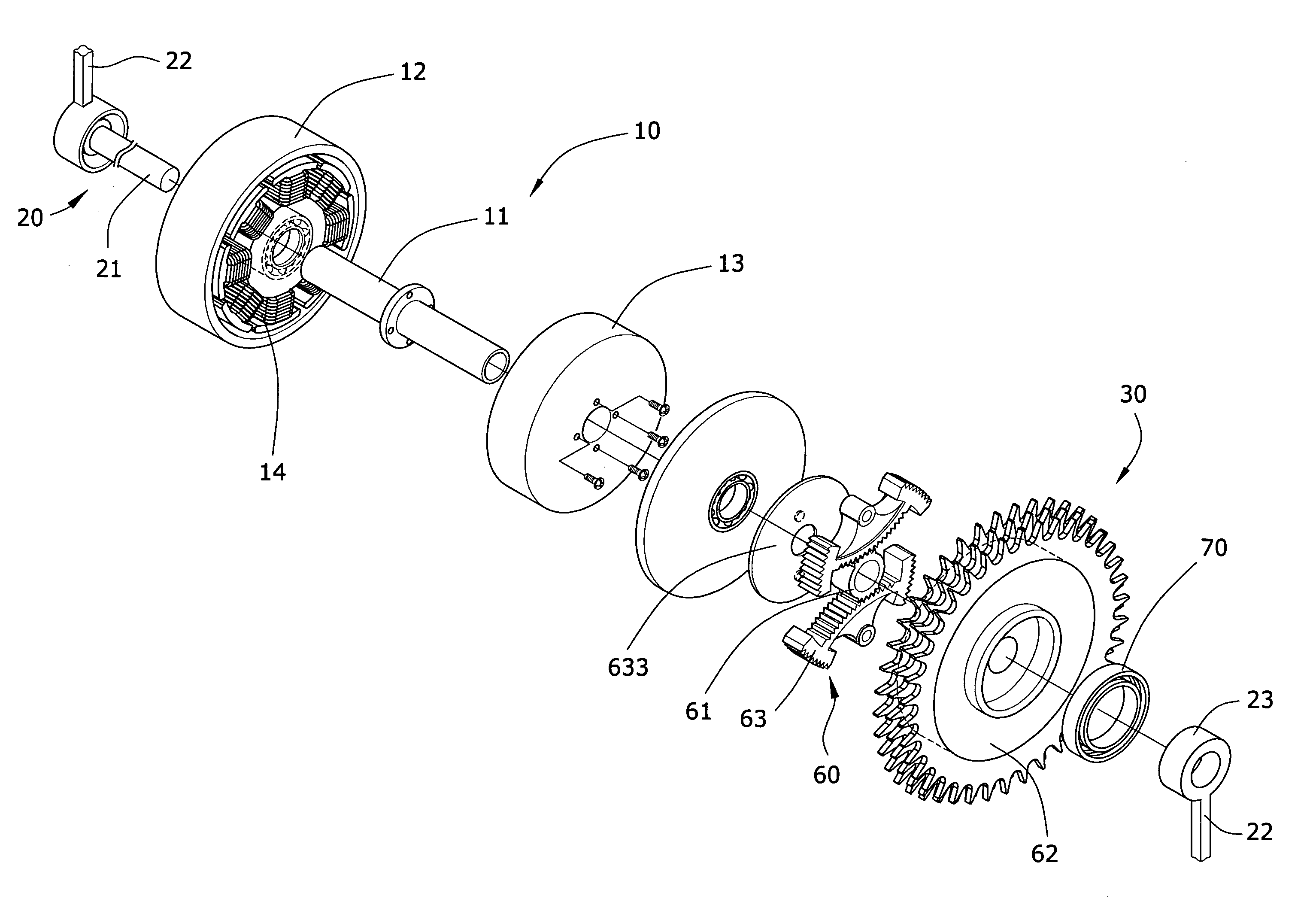
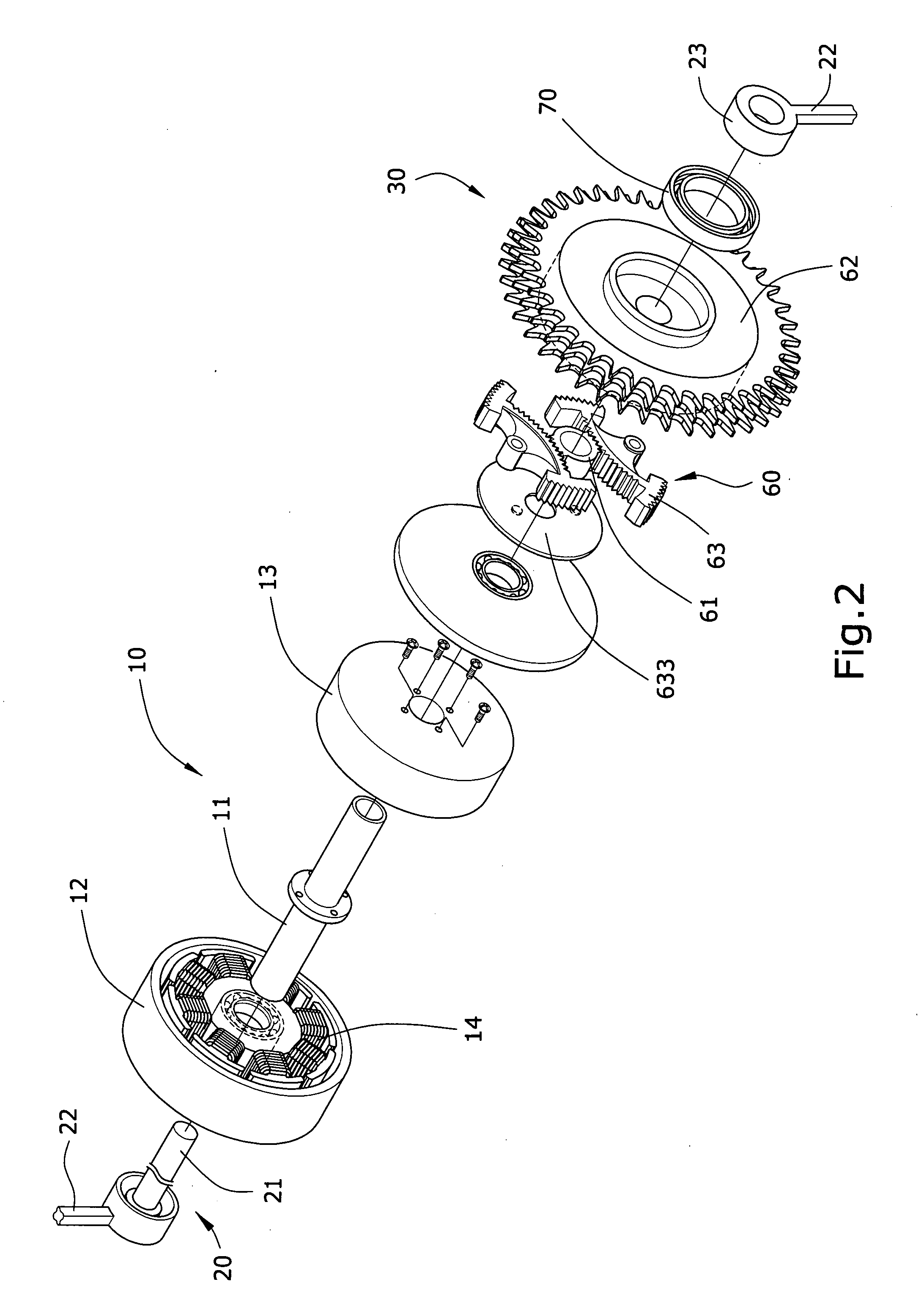
[0019]Referring to FIGS. 2 and 3, which show a feasible embodiment of a transmission structure of the present invention, primary structure and characteristics of which include: a rotating shaft 11 of the electric mechanism 10 that is a hollow tube which passes through two sides of the electric mechanism 10; a pedal shaft 21 of the pedal mechanism 20 that penetrates and is disposed within the aforementioned rotating shaft 11, and which is able to rotate ...


PUM


Abstract

An improved structure of a transmission structure for an electrically operated bicycle, structured to include an electric mechanism and a pedal coaxially disposed on a pedal shaft of a bicycle. The present invention is characterized in that: a rotating shaft of the electric mechanism is a hollow tube that passes through two sides of the electric mechanism; the pedal shaft of the pedal mechanism penetrates and is disposed within the rotating shaft and is able to rotate therein; and the driving chain wheel is pivotal disposed on an outer side of the rotating shaft. One side of the driving chain wheel is coupled to the rotating shaft of the electric mechanism by means of a clutch, and the other side of the driving chain wheel is coupled to a pedal crank of the pedal mechanism by means of a unilateral bearing.

Description

BACKGROUND OF THE INVENTION[0001](a) Field of the Invention[0002]The present invention relates to an improved structure of a transmission structure for an electrically operated bicycle, and more particularly to a transmission structure that is simple, output torque is large, and enables automatic switching between electrical operation and pedal operation, thereby enabling a bicycle to achieve effectiveness to easily move forward.[0003](b) Description of the Prior Art[0004]In general, electrically operated bicycles of prior art use a design that separates the electric mechanism from the manual pedal mechanism, which separately actuate a rear wheel to achieve the objective of moving the bicycle forward. A shortcoming of such prior art structures is that a switching device must be provided between the electrical operating means and the pedal operating means to control interchange between the two mechanisms. Hence, prior art structures are more complex, and relatively inconvenient in us...

Claims


Application Information

Patent Timeline
Patent Type & Authority Applications(United States)
IPC IPC(8): B60W10/02B60W10/18B62M6/55
CPCB62M6/55Y10T477/26Y10T477/24B62M11/145
Inventor PERNG, TE-YU
Owner PERNG TE YU
Learn More